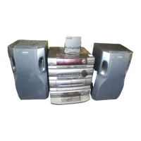
Do you have a question about the Sony LBT-A590 and is the answer not in the manual?
Details specific models included in this service manual: AEP, E, Australian, and PX.
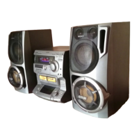
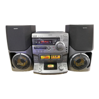
Lists component model names within the LBT-A590/A595 system.
Details DIN power output, continuous RMS power, and music power specifications.
Lists input sensitivity, impedance, output specifications, and frequency response.
Specifies power requirements for different regions and power consumption.
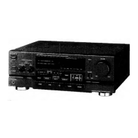
Identifies the location of all controls on the front panel of the unit.
Provides instructions for disassembling the unit.
Contains block diagrams, wiring boards, and schematic diagrams.
Illustrates the physical layout of parts for exploded views.
Lists all electrical components with part numbers.
Highlights critical components vital for safe operation and replacement.
Details the procedure for disassembling the front panel assembly.
Presents the functional block diagram of the system.
Provides reference numbers and locations for semiconductors on the board.
Illustrates the physical placement of various circuit boards within the unit.
Shows the block diagram for IC201, the MC14052BCP.
Presents the block diagram for IC250, the TC4094BP.
Illustrates the block diagram for IC702, the PC1237HA.
Block diagram for the audio board IC102 MC14052BCP.
Block diagram for IC501, the MS289P.
Block diagram for IC502, the NJU7305L.
Block diagram for IC903, the XR1091DCP.
Block diagram for IC904, the LB1639.
Lists semiconductor reference numbers and their locations on the printed wiring boards.
Detailed pin description for IC901 on the Panel A board.
Lists the applicable models: E, East European, CIS, Australian, PX, and Tourist.
Details tuner system, frequency response, antenna, and tuning range.
Covers power requirements, power consumption, weight, and dimensions.
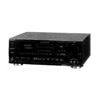
Identifies the location of controls on the ST-A790 tuner.
Notes on power supply usage during servicing.
Provides diagrams including IC pin functions and board locations.
Exploded view of the tuner's cabinet section.
Exploded views of the tuner's components.
Lists all electrical parts for the tuner.
Details procedures and precautions for mechanical adjustments like head cleaning and screw adjustments.
Provides procedures for electrical adjustments, including playback level and tape speed.
Procedure for adjusting playback level for both decks.
Procedure for adjusting bias current for Deck B.
Procedure for adjusting record level and L/R balance for Deck B.
Detailed pinout description for IC801 on the Main Board.
Provides block diagrams for various ICs used in the tuner section.
Lists semiconductor reference numbers and their locations on the printed wiring boards.
Illustrates the lead layouts for semiconductors used in the MD section.
Exploded view of the unit's case and chassis components.
Exploded view and part list for the Deck A mechanism.
Exploded view and part list for the Deck B mechanism (TC-A590).
Exploded view and part list for the Deck B mechanism (TC-A790).
Exploded view and part list for the Deck A mechanism.
Exploded view and part list for the Deck B mechanism (TC-A590).
Exploded view and part list for the Deck B mechanism (TC-A790).
Lists the applicable models: E, East European, CIS, Australian, PX, and Tourist.
Details tuner system, frequency response, antenna, and tuning range.
Covers power requirements, power consumption, weight, and dimensions.
Identifies the location of controls on the ST-A790 tuner.
Notes on power supply usage during servicing.
Provides diagrams including IC pin functions and board locations.
Exploded view of the tuner's cabinet section.
Exploded views of the tuner's components.
Lists all electrical parts for the tuner.
General precautions before performing electrical adjustments.
Procedure for adjusting AM tuning level.
Procedure for adjusting FM tuning level.
Procedure for FM polar adjustment specific to CIS models.
Detailed pinout description for IC601, the System Control Microprocessor.
Lists semiconductor reference numbers and their locations on the tuner boards.
Provides block diagrams for various ICs used in the tuner section.
Lists semiconductor reference numbers and their locations on the display boards.
Block diagram for IC801, the LA5667.
Lists semiconductor reference numbers and their locations on the power supply boards.
Lists applicable models: AEP, E, and Australian.
Details model names, CD mechanism type, base unit, and optical pick-up.
Covers power requirements, power consumption, weight, dimensions, and supplied accessories.
Precautions for handling the optical pick-up block to prevent electrostatic damage.
Guidelines for checking laser diode emission safely.
Highlights critical components vital for safe operation and replacement.
Identifies the location of controls on the CD player.
Notes on replacing chip components and tantalum capacitors.
Guidelines for repairing flexible circuit boards.
Contains diagrams including IC pin functions and board layouts.
Exploded view of the CD player's cabinet section.
Exploded views of the CD player's components.
Lists all electrical parts for the CD player.
Procedure for checking the S-curve waveform symmetry and peak level.
Procedure for checking the RF signal level and waveform clarity.
Procedure for checking the E-F balance waveform symmetry.
Procedure for checking the RF PLL free-run frequency.
Diagram showing the location of circuit boards.
Illustrates the lead layouts for semiconductors.
Provides block diagrams for ICs used in the main section.
Highlights components marked with A or dotted lines that are critical for safety.
Lists semiconductor reference numbers and their locations on the main boards.
Detailed pinout description for IC101, the Digital Servo & DSP.
Highlights components critical for safety that require specific part numbers for replacement.
Lists applicable models: AEP and E.
Details model names, CD mechanism type, base unit, and optical pick-up.
Covers power requirements, power consumption, weight, dimensions, and supplied accessories.
Identifies the location of controls on the CD player.
Notes on replacing chip components and tantalum capacitors.
Guidelines for repairing flexible circuit boards.
Provides diagrams including IC pin functions and board layouts.
Exploded view of the CD player's cabinet section.
Exploded views of the CD player's components.
Lists all electrical parts for the CD player.
Highlights critical components vital for safe operation and replacement.
Precautions for handling the optical pick-up block to prevent electrostatic damage.
Guidelines for checking laser diode emission safely.
Identifies the location of controls on the CD player.
Describes buttons for cassette deck control.
Describes buttons for tuner control, including preset selection.
Describes buttons for CD player control, including numeric and function buttons.
Explains the function of numeric buttons in tuner and CD player modes.
Procedure for checking the S-curve waveform symmetry and peak level.
Procedure for checking the RF signal level and waveform clarity.
Procedure for checking the E-F balance waveform symmetry.
Procedure for checking the RF PLL free-run frequency.
Diagram showing the location of circuit boards.
Illustrates the lead layouts for semiconductors.
Lists semiconductor reference numbers and their locations on the boards.
Provides block diagrams for ICs used in the main section.
Highlights components marked with A or dotted lines that are critical for safety.
Lists semiconductor reference numbers and their locations on the main boards.
Detailed pinout description for IC101, the Digital Servo & DSP.
Highlights components critical for safety that require specific part numbers for replacement.
Lists applicable models: AEP and E.
Details model names, CD mechanism type, base unit, and optical pick-up.
Covers power requirements, power consumption, weight, dimensions, and supplied accessories.
Identifies the location of controls on the CD player.
Notes on replacing chip components and tantalum capacitors.
Guidelines for repairing flexible circuit boards.
Provides diagrams including IC pin functions and board layouts.
Exploded view of the CD player's cabinet section.
Exploded views of the CD player's components.
Lists all electrical parts for the CD player.
Highlights critical components vital for safe operation and replacement.
Precautions for handling the optical pick-up block to prevent electrostatic damage.
Guidelines for checking laser diode emission safely.
Identifies the location of controls on the CD player.
Describes buttons for cassette deck control.
Describes buttons for tuner control, including preset selection.
Describes buttons for CD player control, including numeric and function buttons.
Explains the function of numeric buttons in tuner and CD player modes.
Procedure for checking the S-curve waveform symmetry and peak level.
Procedure for checking the RF signal level and waveform clarity.
Procedure for checking the E-F balance waveform symmetry.
Procedure for checking the RF PLL free-run frequency.
Lists semiconductor reference numbers and their locations on the boards.
Provides block diagrams for ICs used in the main section.
Highlights components marked with A or dotted lines that are critical for safety.
Lists semiconductor reference numbers and their locations on the main boards.
Detailed pinout description for IC101, the Digital Servo & DSP.
| Type | Stereo System |
|---|---|
| CD Player | Yes |
| Bluetooth | No |
| USB Playback | No |
| FM Radio | Yes |
| Tuner Bands | FM/AM |
| Tape Deck | Yes |
| Remote Control | Yes |
| Radio | Yes |
| Cassette Deck | Yes |
| Speakers | 2 Speakers |