EasyManua.ls Logo

Sony LBT-A57CD User Manual

Sony LBT-A57CD
92 pages
To Next Page IconTo Next Page
Page #1 background imageLoading...
Page #1 background image
LBT-A570D/A57CDM/AG7CD/AG7COM
SERVICE
MANUAL
REVISED
Discard
your
LBT-A57CD/A57CDM/A67CD/
A67CDM/D509CD/D559CD/D609CD
service
manual
previously
issued.
This
service
manual
contain
it.
These
systems
are
composed
of
following
models.
As
for
the
service
manual,
it
is
issued
for
each
component
model,
then,
please
refer
to
it.
COMPONENT
MODEL
NAME
FOR
LBT-A57CD/
/0509CD/0559C0/D609CD
AEP
Model
LBT-D509CD/D609CD
UK
Model
LBT-D559CD
E
Model
LBT-A57CD/A57CDM/A67CD/A67CDM
Australian
Model
LBT-A57CDM/A67CDM
A57CDM/D509CD/D559CD
System
|
|
UBT-A57CD
|
LBT:A57CDM
|
LBT:D509C0
|
LBT-D559CD
Component
|
|
|
Tuner
ST-0709 sT-D709
Amplifier
TA-A57
TA-D509
Cassette
deck
TC-D509 TC-D509
TC-D609
Record
player
|
=
PSLx47P_
|
CD
player
CDP-M43
CDP-C422M
eae
eae
CDP-C422M
|
COMPONENT
Mi
A67CDM/D609CD
IODEL
NAME
FOR
LBT-AG7CD/
Component
System
LBT-A67CD
|
LBT-A67CDM
|
LBT-D609CD
Tuner
ST-D709
Amplifier
TAAG7
Cassette
deck
TC-D709
TA-D609
CD
player
CDP-M43
|
CDP.C422M
CDP-M43
or
CDP-C422M
STEREO
COMPONENT
SYSTEM
SONYY.
Question and Answer IconNeed help?

Do you have a question about the Sony LBT-A57CD and is the answer not in the manual?

Sony LBT-A57CD Specifications

General IconGeneral
TypeStereo System
CD PlayerYes
Remote ControlYes
BluetoothNo
USB PlaybackNo
Tape DeckYes
TunerYes (AM/FM)
SpeakersYes

Summary

Parts List

Accessories & Packing Materials

Lists all parts and accessories included with the product models.

Specifications

TA-A57 Specifications

Technical details for the TA-A57 amplifier section.

TA-D509 Specifications

Technical details for the TA-D509 amplifier section.

Section 1 General

1-1. Location of Controls

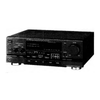
Identifies front panel controls and their functions.

Model Identification

Details for identifying the product model and its variations.

Section 2 Service Notes

2-1. Removal of Fan Case

Procedure for removing the fan case, specific to UK models.

2-2. Removal of Joint

Procedure for removing the joint mechanism.

Section 3 Diagrams

3-1. Circuit Boards Location

Illustrates the location of various circuit boards within the unit.

3-2. Semiconductor Lead Layouts

Pin configurations for various semiconductor components.

3-3. Printed Wiring Boards-Main Section-

Shows the layout of the main printed wiring board.

3-4. Schematic Diagram-Main Section-

Electrical schematic diagram for the main section.

Section 4 Exploded Views

4-1. Front Panel Section

Exploded view of the front panel assembly and parts.

4-2. Chassis Section

Exploded view of the chassis assembly and parts.

Section 5 Electrical Parts List

Specifications (CDP-M43/M54)

Compact Disc Player Specifications

Technical details for the compact disc player.

Model Identification (CDP-M43/M54)

Handling Optical Pick-Up Block

Precautions for handling the sensitive optical pick-up unit.

Laser Diode Emission Check

Safety guidelines for checking laser diode emission.

Section 1 General (CDP-M43/M54)

1-1 Identifying the Parts

Identifies front panel and remote control parts.

1-2 Setting the Clock

Instructions for setting the unit's clock.

Section 2 Disassembly (CDP-M43/M54)

Section 3 Electrical Block Checking (CDP-M43/M54)

S Curve Check

Procedure for checking the S-curve waveform.

RF Level Check

Procedure for checking RF signal levels.

Section 4 Diagrams (CDP-M43/M54)

4-1 Block Diagram

Overall block diagram of the system's functionality.

4-2 Circuit Boards Location

Visual guide to the location of all circuit boards.

4-3 Semiconductor Lead Layouts

Pin configurations for semiconductor components.

4-4 Printed Wiring Boards

Layouts of the unit's printed wiring boards.

Section 5 Exploded Views (CDP-M43/M54)

5-1 Cabinet Section

Exploded view of the cabinet and its components.

5-3 Optical Pick-Up Block (BU-55BD8A)

Exploded view of the optical pick-up block.

Section 6 Electrical Parts List (CDP-M43/M54)

BD Electrical Parts List

Detailed parts list for the BD board.

Difference Parts List (TC-D507)

Specifications (TC-D507)

Section 1. General (TC-D507)

1-1. Location of Controls

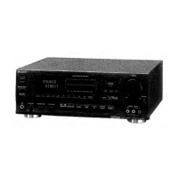
Identifies controls on the TC-D507 unit.

Section 3 Mechanical Adjustments (TC-D507)

Section 4 Electrical Adjustments (TC-D507)

Test Mode

How to enter and use the unit's test mode for adjustments.

Section 5 Diagrams (TC-D507)

5-1. Circuit Boards Location

Illustrates the location of circuit boards for the TC-D507.

5-2. Semiconductor Lead Layouts

Pin configurations for TC-D507 semiconductor components.

Specifications (ST-D709)

Section 1 General (ST-D709)

1-1. Location of Controls

Identifies controls on the ST-D709 tuner.

Section 2 Electrical Adjustments (ST-D709)

FM Section

Adjustments and information specific to the FM tuner section.

Section 3 Diagrams (ST-D709)

3-1. Semiconductor Lead Layouts

Pin configurations for ST-D709 semiconductor components.

Section 4 Exploded View (ST-D709)

Miscellaneous

Hardware List

List of miscellaneous hardware components.

Related product manuals