EasyManua.ls Logo

Sony LBT-A795 User Manual

Sony LBT-A795
131 pages
To Next Page IconTo Next Page
Page #1 background imageLoading...
Page #1 background image
LBT-A790/A7995
SERVICE
MANUAL
AEP
Model
LBT-A790
E
Model
LBT-A790/A795
Australian
Model
LBT-A795
Tourist
Model
LBT-A790
+
LBT-A790/A795
are
composed
of
following
models.
As
for
the
service
manual,
it
is
issued
for
each
component
model,
then,
please
refer
to
it.
COMPONENT
MODEL
NAME
FOR
THESE
SYSTEM
LBT-A790
LBT-A795
aeP|
it
|
@
[cis]
|
ea]
sP
|
my
JE
E
[mx
[aus
POWER-AMPLIFIER
TA-A790N
PRE-AMPLIFIER
TA-A790E
CASSETTE
DECK
TC-A790
TUNER
ST-A790
CD
PLAYER
CDP-M46
CDP-C433M
SPEAKER
SYSTEM
$S-D790AN
AUS
:
Australian
IT:
Italian
MX
=:
Mexican
BA
:
Saudi
Arabia
G
:
German
MY
:
Malaysia
SP:
Singapore
JE
:
Tourist
STEREO
COMPONENT
SYSTEM
ONY.
English
94D0570-1
Sony
Corporation
Printed
in
Japan
Comsumer
A&V
Products
Company
©
1994.4
9-959-479-11
Home
A&V
Products
Div.
Published
by
Home
A&V
Products
Div.
Quality
Engineering
Dept.
Question and Answer IconNeed help?

Do you have a question about the Sony LBT-A795 and is the answer not in the manual?

Sony LBT-A795 Specifications

General IconGeneral
BrandSony
ModelLBT-A795
CategoryStereo System
LanguageEnglish

Summary

Specifications

Safety-Related Component Warning

Warning about critical components for safe operation and replacement instructions.

General

Location of Controls

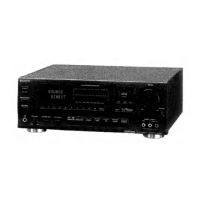
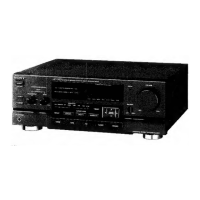
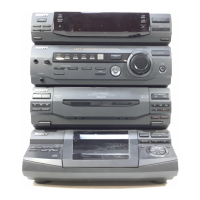
Identifies controls and indicators on the front panel of the cassette deck.

Service Note

Removal of Joint

Procedure for removing a specific joint component during disassembly.

Diagrams

IC Pin Descriptions

Details the function and I/O for each pin of specified ICs.

Circuit Boards Location

Diagram showing the physical location of various circuit boards within the unit.

Block Diagram

Functional block diagram illustrating the system's signal flow.

Semiconductor Lead Layouts

Illustrations of semiconductor component pin configurations for identification.

Printed Wiring Boards

Layout of printed wiring boards showing component placement and connections.

Schematic Diagram

Detailed schematic circuit diagram illustrating the unit's circuitry.

Printed Wiring Boards - Main Section

Layout of the main printed wiring board showing component placement and connections.

Schematic Diagram - Main Section

Detailed schematic circuit diagram for the main section of the unit.

Schematic Diagram - Panel Section

Detailed schematic circuit diagram for the panel section of the unit.

Printed Wiring Boards - Panel Section

Layout of the panel section printed wiring board showing component placement.

Exploded Views

Front Panel Section Exploded View

Exploded view of the front panel assembly, detailing its components.

Chassis Section Exploded View

Exploded view of the chassis and internal parts, including their assembly.

Electrical Parts List

Electrical Adjustments

Exploded View

Servicing Note

Electrical Block Checking

Safety-Related Component Warning

Disassembly

Adjustments

Main Section Printed Wiring Boards

MD Section Printed Wiring Boards

Exploded View and Parts List

Related product manuals