10
D-E221/E223
S804
ON
OFF
ESP
J302
TP629
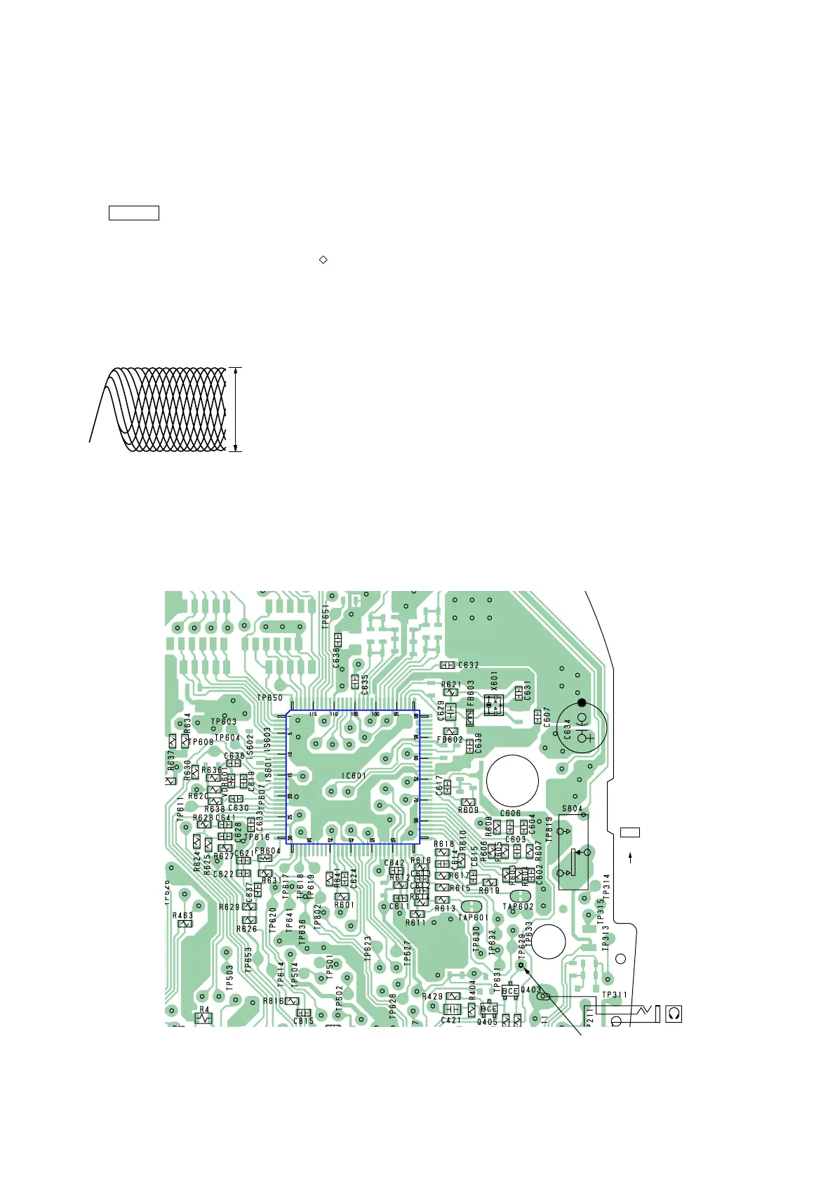
– MAIN BOARD – (SIDE B)
RF level :
0.5
±
0.1 Vp-p
VOLT/DIV : 20 mV (10 : 1 probe in use)
TIME/DIV : 500 nS
SECTION 4
ELECTRICAL ADJUSTMENTS
CD section adjustments are done automatically in this set.
In case of operation check, confirm that focus bias.
4-1. FOCUS BIAS CHECK
1. Connect the oscilloscope between TP629 (RF) and GND on
main board.
2. Insert the disc (YEDS-18). (Part No. : 3-702-101-01)
3. Press the > N button.
4. Confirm that the oscilloscope waveform is as shown in the
figure below. (eye pattern)
A good eye pattern means that the diamond shape ( ) in the
center of the waveform can be clearly distinguished.
• RF signal reference waveform (eye pattern)
Test Points:
When observing the eye pattern, set the oscilloscope for AC range
and raise vertical sensitivity.