er”, Switch unit
“Motor ASSY, Turn table (Spindle) (M901)”,
Optical pick-up (DAX-23E), “Motor ASSY (Sled) (M902)”
Cabinet (front)
Set
SECTION 3
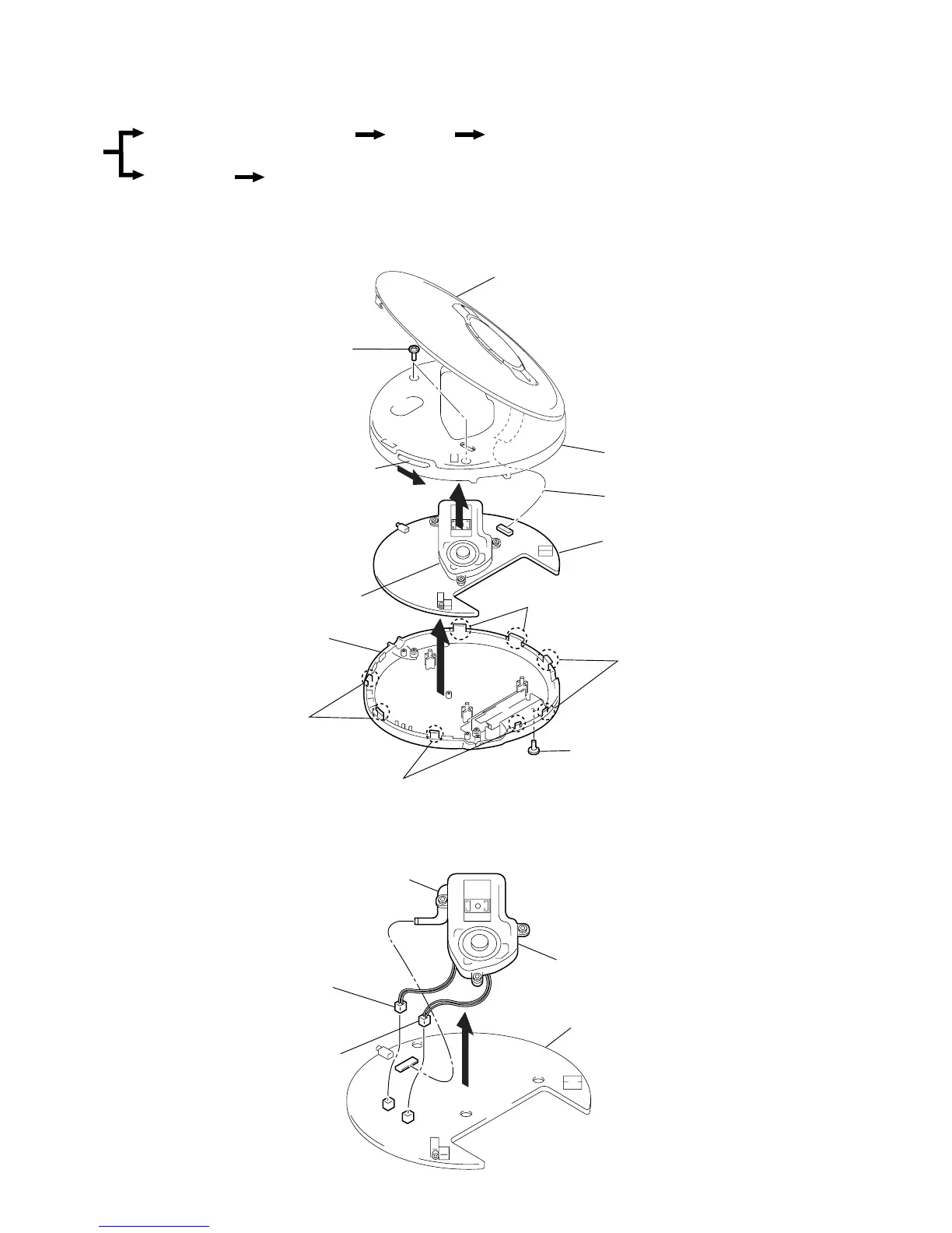
DISASSEMBLY
Note : Follow the disassembly procedure in the numerical order given.
3-1. CABINET (REAR) SUB ASSY, CABINET (FRONT), MAIN BOARD
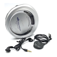
3-2. MD ASSY
z
The equipment can be removed using the following procedure.
4
1
CN502 (Green)
2
CN503 (White)
3
Optical pick-up flexible board
MD ASSY
Main board
3
Screws (B2)
5
7
1
Screw (B2)
2
OPEN
6
Flexible board (CN801)
Lid, Upper
Cabinet (Front)
Main board
MD ASSY
Cabinet (Rear) sub ASSY
4
Claws
4
Claws
4
Claws
4
Claws