– 9 –
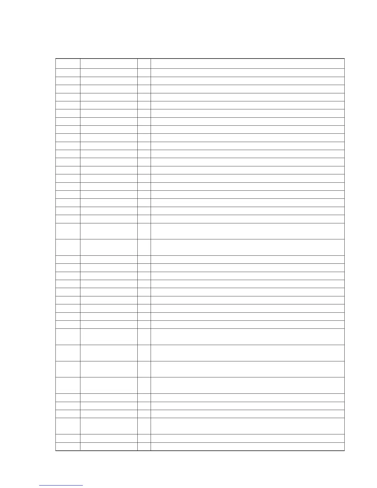
Pin No. Pin name I/O Description
1 VSS — Ground terminal.
2 IRRMCO — Not used (OPEN).
3 FOKI I Focus OK signal input from the digital servo processor (IC601). “L”: NG, “H”: OK
4 AGCPWM O AGC control pulse signal output terminal.
5 RESERVE — Not used (OPEN).
6 RESERVE — Not used (OPEN).
7 AMUTE O Analog audio muting ON/OFF control signal output terminal. “H”: muting ON
8 VCC2 ON O VCC2 voltage control signal output terminal.
9 XRST O Reset signal output to IC601. “L”: reset
10 SCK O Serial data transfer clock signal output to IC601.
11 MSDTI I Serial data input from the IC601.
12 MSDTO O Serial data output to IC601.
13 WAKE UP O WAKE-UP control signal output terminal (for system standby reset).
14 SEL I Plug-in detection signal input terminal of LINE OUT/OPTICAL OUT.
15 CHGMNT I Battery charge voltage detection input from the power control (IC401).
16 KEY2 I Volume key input terminal.
17 BATMNT I Battery voltage detection signal input terminal
18 KEY1 I Key input terminal.
19 RMKEY I Key input from the headphone with remote commander (A/D input).
20 DCINMNT I
DC input voltage detection input terminal (A/D input) and DC input jack use/no use
detection input terminal.
21 OPEN I
CD door open/close detection switch (S801) input terminal.
The stop status is reset with the falling edge of input signal.
22 VREFL I Reference voltage input terminal (0V) for A/D converter.
23 VREFH I Reference voltage input terminal (+2V) for A/D converter.
24 VDD — Power supply terminal (+2V).
25 SCOR I Sub-code sync (S0+S1) detection signal input from the IC601.
26 GRSCOR I GRSCOR signal input from the IC601.
27 FG I FG pulse signal input.
28 BEEP O Beep sound output to the headphone amplifier (IC302).
29 RESERVE — Not used ( Fixed at “H”).
30 RMSCK O Communication clock output to the communication format converter (IC802).
31 RMDATI I
Communication data bus input of headphone with remote commander from the communi-
cation format converter (IC802).
32 RMDATO O
Communication data bus output of headphone with remote commander to the communi-
cation format converter (IC802).
33 RMRW O
Read/write control signal output of headphone with remote commander to the communi-
cation format converter (IC802). “L”: read mode, “H”: write mode
34 RMLAT O
Serial data latch pulse signal output of headphone with remote commander to the commu-
nication format converter (IC802).
35 WFCKI I WFCK signal input from the IC601.
36 COMPRESSION I G PROTECTION switch input.
37 SLVCD I Not used (Fixed at “H”).
38 AVLS I
AVLS (Automatic Volume Limiter System) switch (S803) input terminal.
“L”: normal mode, “H”: limit mode
39 HOLD I HOLD switch (S803) input terminal. “L”: hold ON, “H”: hold OFF
40 BATT DET I External battery detection signal input terminal.
SECTION 5
DIAGRAMS
5-1. EXPLANATION OF IC TERMINALS
IC801 (SYSTEM CONTROLLER) TMP88CM22F-MIR1-1