6
D-EJ011
SECTION 4
ELECTRICAL ADJUSTMENTS
The CD section adjustments are done automatically in this set.
Adjusting Procedure:
1. Perform check in the order given.
2. Use YEDS-18 disc (Part No: 3-702-101-01) unless otherwise
indicated.
3. Power supply voltage requirement :DC4.5 V in DC IN jack.
(J401)
VOLUME button : Minimum
HOLD switch :OFF
Focus bias Check
Condition:
• Hold the set in horizontal state.
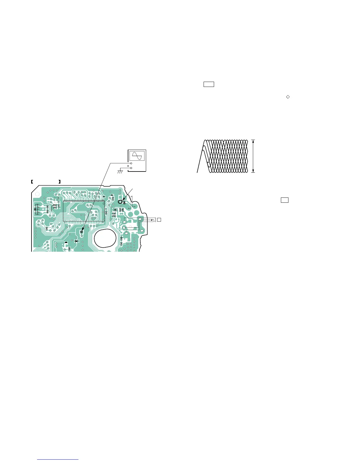
Connection:
Procedure:
1. Make a solder bridge to short SL801 (OPEN) on the MAIN
board side B.
2. Connect the oscilloscope to the test point TP604 (EQOUT)
and TP406 (M-GND) on the MAIN board side B.
3. Set a disc. (YEDS-18)
4. Press the u button.
5. Check the oscilloscope waveform is as shown below.
A good eye pattern means that the diamond shape ( ) in the
center of the waveform can be clearly distinguished.
RF Signal reference Waveform (Eye Pattern)
To watch the eye pattern, set the oscilloscope to AC range and
increase the vertical sensitivity of the oscilloscope for easy
watch-ing.
6. Stop revolving of the disc motor by pressing the x button.
7. SL801 is opened by taking the solder bridge.
RF level
1.3
±
0.2 Vp-p
VOLT/DIV : 500 mV (With the 10 : 1 probe in use