EasyManua.ls Logo

Sony D-EJ1000 User Manual

Sony D-EJ1000
32 pages
To Next Page IconTo Next Page
Page #1 background imageLoading...
Page #1 background image
D-EJ1000
US Model
Canadian Model
AEP Model
UK Model
E Model
Australian Model
Chinese Model
Tourist Model
SERVICE MANUAL
PORTABLE CD PLAYER
Sony Corporation
Personal Audio Company
Published by Sony Engineering Corporation
9-873-395-01
2001J1600-1
© 2001.10
SPECIFICATIONS
Ver 1.0 2001. 10
Model Name Using Similar Mechanism NEW
CD Mechanism Type CDM-3325ES
Optical Pick-up Name DAX-25E
System
Compact disc digital audio system
Laser diode properties
Material: GaAlAs
Wavelength: λ = 780 nm
Emission duration: Continuous
Laser output: Less than 44.6 µW
(This output is the value measured at a distance
of 200 mm from the objective lens surface on
the optical pick-up block with 7 mm aperture.)
D-A conversion
1-bit quartz time-axis control
Frequency response
20 - 20 000 Hz
+1
–2
dB (measured by JEITA CP-
307)
Output (at 4.5 V input level)
Line output (stereo minijack)
Output level 0.7 V rms at 47 k
Recommended load impedance over 10 k
Headphones (stereo minijack)
Approx. 5 mW + Approx. 5 mW at 16
(Approx. 0.5 mW + Approx. 0.5 mW
at 16
)*
*For the customers in France
Optical digital output (optical output connector)
Output level: –21 - –15 dBm
Wavelength: 630 - 690 nm at peak level
Power requirements
For the area code of the model you
purchased, check the upper left side of the
bar code on the package.
Two Sony NH-14WM (A) rechargeable
batteries: 2.4 V DC
Two LR6 (size AA) batteries: 3 V DC
AC power adaptor (DC IN 4.5 V jack):
U/U2/CA2/E92/MX2/TW2/BR3 model:
120 V, 60 Hz
CED/CET/CEW/CEX/CE7/EE/EE1/E13/G5/
G6/G7/G8/BR1 model: 220 - 230 V, 50/60 Hz
CEK/3CE7 model: 230 - 240 V, 50 Hz
AU2 model: 240 V, 50 Hz
JE.W/E33/EA3/KR4 model: 100 - 240 V,
50/60 Hz
HK2 model: 220 V, 50/60 Hz
AR1/CN2 model: 220 V, 50 Hz
Battery life* (approx. hours)
(When you use the CD player on a flat and stable
surface.)
Playing time varies depending on how the CD
player is used.
When using G-PROTECTION
“1” “2”
Two NH-14WM (A) 40 41
(charged for
about 5 hours**)
External battery case 66 71
(two alkaline batteries***)
Rechargeable batteries 108 115
NH-14WM (A) and
external battery case
(two alkaline batteries***)
* Measured value by the standard of JEITA (Japan
Electronics and Information Technology
Industries Association).
** Charging time varies depending on how the
rechargeable battery is used.
*** When using Sony alkaline batteries LR6 (SG)
(produced in Japan)
Operating temperature
5°C - 35°C (41°F - 95°F)
Dimensions (w/h/d) (excluding
projecting parts and controls)
Approx. 127.0 × 136.2 × 13.9 mm
(5 × 5
3
8
×
9
16
in.)
Mass (excluding accessories)
Approx. 129 g (4.6 oz)
Design and specifications are subject to change
without notice.
Question and Answer IconNeed help?

Do you have a question about the Sony D-EJ1000 and is the answer not in the manual?

Sony D-EJ1000 Specifications

General IconGeneral
TypePortable CD Player
Anti-ShockYes
Anti-skipYes
Frequency Response20 Hz - 20 kHz
Signal-to-Noise Ratio90 dB
Dynamic Range90 dB
DisplayLCD
Disc formatCD, CD-R, CD-RW
OutputHeadphone output (stereo mini jack)
Power2 x AA Batteries
Playback FormatsCD-DA

Summary

Servicing Notes and Precautions

Handling the Optical Pick-up Block and Laser Diode

Essential notes on safely handling the optical pick-up block and checking laser diode emission.

Service Mode Operations

Setting the Service Mode

Procedure for enabling and configuring the service mode for diagnostic operations.

Service Mode Operations

Details on operating the device and using controls within the service mode.

General Information and Controls

Component Location Guide

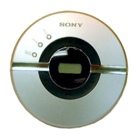
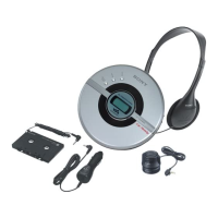
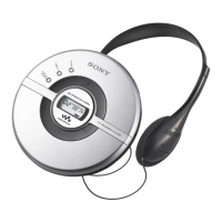
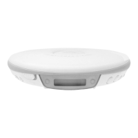
Identifies and locates all external controls and connectors on the CD player and remote.

Disassembly Procedures

Upper Lid Section Disassembly

Step-by-step guide for disassembling the upper lid of the unit.

Cabinet Sections Disassembly

Instructions for disassembling the upper cabinet and the main board/optical pick-up section.

Electrical Checking and Diagnostics

RF Level Checking Procedure

Steps and conditions for checking the RF signal level, including precautions and expected waveforms.

Diagrams and Schematics

Block Diagrams

Detailed block diagrams illustrating the main, power supply, and other sections of the device.

Printed Wiring Boards and Schematics

Printed wiring board layouts and schematic diagrams for key circuit sections.

IC Pin Function Descriptions

Comprehensive descriptions of pin functions for integrated circuits used in the device.

Exploded Views for Assembly

Upper Lid and Cabinet Exploded Views

Exploded views showing the assembly of the upper lid and cabinet sections.

Lower Cabinet and Optical Pick-up Views

Exploded views detailing the lower cabinet and the optical pick-up assembly.

Electrical Parts List

Capacitor List

Detailed list of capacitors used in the device, with part numbers and specifications.

Connectors, Diodes, ICs, and More

Parts list for connectors, diodes, ICs, ferrite beads, jacks, and coils.

Transistors and Resistors List

Comprehensive list of transistors and resistors with their part numbers and values.

Switches, Varistors, and Accessories

Parts list for switches, varistors, and included accessories.

Related product manuals