— 38 —
DV MECHANICAL ADJUSTMENT MANUAL VII
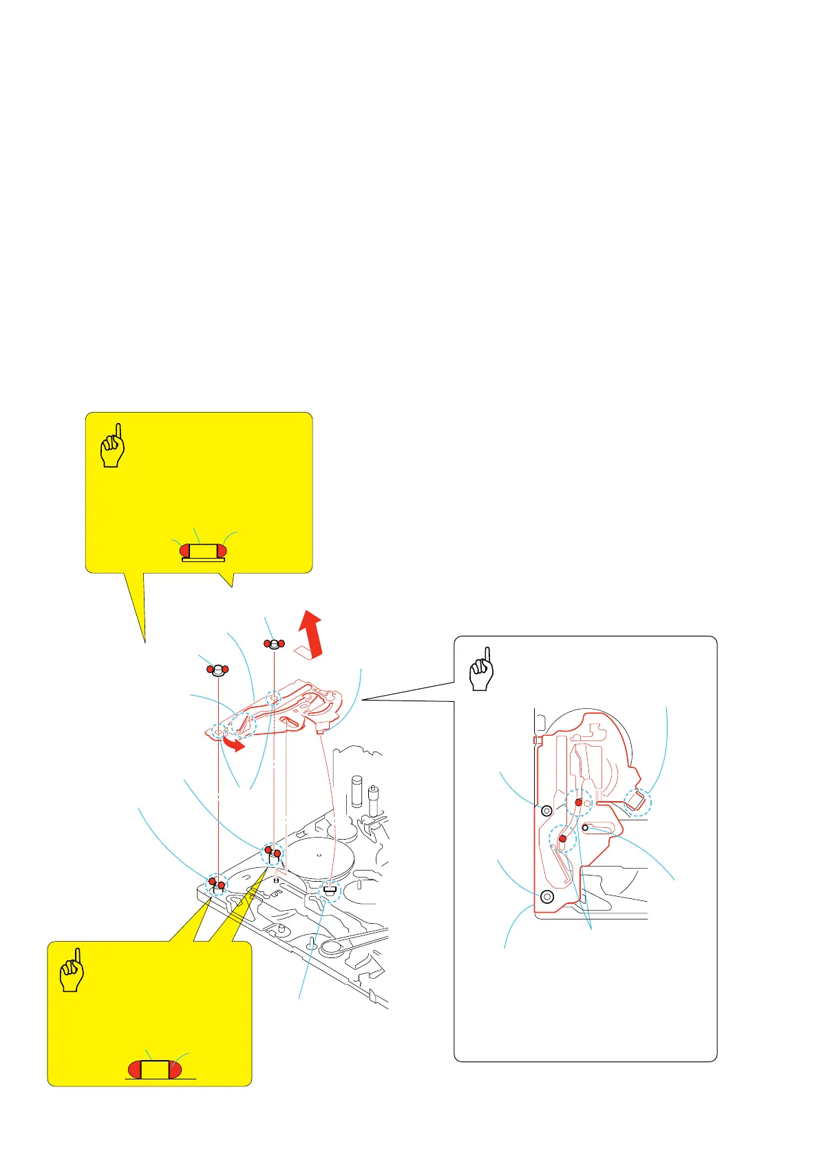
3-27.TG2 Cam Plate Assy
1. Removal procedure
1) Remove the LS guide roller (S1) 1 from the S1 shaft.
2) Remove the LS guide roller (S2) 2 from the S2 shaft.
3) Release the claw A of the TG2 cam plate assy 3 from the
right groove B of the mechanical chassis.
4) Remove the TG2 cam plate assy 3 in the direction of the arrow
C.
2. Attachment procedure
1) Move the brake driving arm of the TG2 cam plate assy 3 in
the direction of the arrow D.
2) Insert the right claw A of the TG2 cam plate assy 3 into the
right groove B of the mechanical chassis first.
3) Install the two round holes E of the TG2 cam plate assy 3
into the S1 shaft and the S2 shaft.
4) Apply grease in the F portion of the TG2 cam plate assy.
Amount of grease: a ball of 1.0 mm diameter of grease
5) Apply grease to both sides of the S1 shaft and the S2 shaft.
Amount of grease: a ball of 1.0 mm diameter of grease
6) Apply grease to both sides of the LS guide roller S1, S2.
7) Install the LS guide roller S1 1 in the S1 shaft.
8) Install the LS guide roller S2 2 in the S2 shaft.
3
TG2 cam
plate assy
1
LS guide roller S1
LS guide roller S1, S2
2
LS guide
roller S2
Brake driving arm
C
D
F
S2 shaft
S2 shaft
S1 shaft
M slider shaft
S1 shaft
S1 shaft, S2 shaft
Apply grease when installing it
Amount of grease: a ball of
1.0 mm diameter of grease
Claw
A
Two round
holes
E
Claw
A
Groove
B
TG2 cam
plate assy
Apply grease
Apply grease
Apply grease
Apply grease when installing it.
Amount of grease: a ball of 1.0 mm
diameter of grease
Apply grease when installing it.
Amount of grease: a ball of 1.0 mm
diameter of grease
TG2 CAM PLATE ASSY
The Points
in Re-assembling
Points to be noted
Points to be noted
• Confirm that the M slider shaft has entered in the
groove of the brake driving arm surely.
• Confirm that the right and left claws of the TG2
cam plate assy
3
have entered into the
mechanical chassis surely.
Apply Grease
Apply Grease