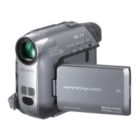
Do you have a question about the Sony DCR-HC39E and is the answer not in the manual?
Records changes and versions of the service manual.
Notes regarding the VC-378 board and its missing content.
Describes the fundamental system parameters of the video camera.
Details the CCD sensor specifications, including pixel count.
Provides specifications for the Carl Zeiss Vario-Tessar lens.
Lists and describes the available input and output connectors.
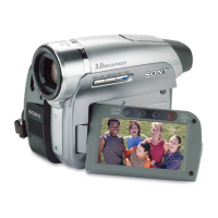
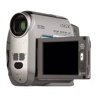
Details the specifications of the LCD panel.
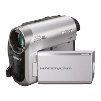
Covers general specifications like power requirements and operating conditions.
Outlines essential safety checks to perform before releasing the unit.
Highlights critical components for safety that require specific SONY parts for replacement.
Explains characteristics and precautions for using unleaded solder.
Provides important notes and precautions for performing repairs.
Details the procedure for manually ejecting a cassette.
Explains the self-diagnosis function for identifying and displaying problems.
Describes how the self-diagnosis function works and displays information.
Explains the format and meaning of the 4-digit self-diagnosis code.
Provides a comprehensive table of self-diagnosis codes, symptoms, and corrections.
Details the overall disassembly flow chart and component removal steps.
Explains how to set the mechanism deck to the correct service position for checks.
Shows the physical locations of various circuit boards within the camera.
Illustrates the locations of flexible boards within the camera assembly.
Presents various block diagrams illustrating the camera's functional architecture.
Displays the overall block diagram for system connectivity.
Shows the power distribution block diagram.
Offers detailed schematic diagrams for specific circuit boards and components.
Shows the physical layout of printed wiring boards for various assemblies.
Indicates the location of mounted parts on specific circuit boards.
Lists all replaceable parts, including exploded views and electrical components.
Illustrates the camera's mechanical parts in exploded views for easy identification.
Details electrical components with their part numbers and descriptions.
Covers initial preparations and checks before performing any adjustments.
Details adjustments related to the camera's optical and image capture systems.
Outlines procedures for adjusting the mechanical tape transport system.
Covers adjustments for video signal processing and output.
Details audio system adjustments specific to models other than DCR-HC39E.
Explains how to access and use the service mode for advanced adjustments.
Covers initial steps and safety precautions for mechanism work.
Details routine maintenance and inspection procedures for the mechanism.
Provides detailed procedures for checking, adjusting, and replacing mechanical components.
Shows exploded views of the mechanism deck for parts identification.
| Fader | Black, White, Mosaic, Overlap, Wipe, Monotone, Random Dot |
|---|---|
| Focus | Auto / Manual |
| I/O ports | USB Audio Out Video Out |
| Sensor type | CCD |
| Total megapixels | 1.07 MP |
| Optical sensor size | 1/5 \ |
| Display diagonal | 2.7 \ |
| Bundled software | Picture Package |
| Camera shutter speed | 1/2-1/3500 s |
| Built-in microphone | Yes |
| Playback zoom (max) | Yes x |
| Battery type | NP-FP50 |
| Video formats supported | MPEG1 |
| DV port | - |
| S-Video in | No |
| Camcorder tape type | Mini-DV |
| Depth | 112 mm |
|---|---|
| Width | 55 mm |
| Height | 90 mm |
| Weight | 410 g |