Do you have a question about the Sony DCR-HC36 and is the answer not in the manual?
Details about video, still, and audio recording systems.
Ports for audio, video, and USB connectivity.
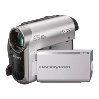
List of items included with the camcorder.
Method to prevent power shut-off during repairs.
Procedure to force eject a cassette.
How to enable forced power on for camera/VTR.
Instructions for using the service jig.
Explanation of the self-diagnosis function and display.
Precautions for replacing the VC-417 board and Exif Model Data check.
General notes for repair and disassembly procedures.
Exploded view and parts list for the overall camera assembly.
Exploded view of the right cabinet block and its components.
Exploded view of the main camera block components.
Exploded view of the main camera block components.
Method for attaching flexible boards/harnesses.
System overview diagram illustrating signal flow.
System overview diagram illustrating signal flow.
System overview diagram illustrating signal flow.
System overview diagram illustrating signal flow.
System overview diagram illustrating signal flow.
System overview diagram illustrating signal flow.
Power supply block diagram illustrating voltage distribution.
Power supply block diagram illustrating voltage distribution.
Power supply block diagram illustrating voltage distribution.
Circuit and wiring diagrams for the CD-632 CCD Imager board.
Circuit and wiring diagrams for the PD-282 LCD Drive/Backlight board.
Circuit and wiring diagrams for the FP-380 flexible board.
Circuit and wiring diagrams for the FP-386 flexible board.
Circuit and wiring diagrams for the SB9000 control key block.
Circuit and wiring diagrams for the SI-052 board.
Circuit and wiring diagrams for the LB-122 board.
Circuit and wiring diagrams for the MS-312 board.
Circuit and wiring diagrams for the FP-381 flexible board.
Circuit and wiring diagrams for FP-031, FP-032, FP-228 boards.
Circuit and wiring diagrams for the CF17000 control key block.
Circuit and wiring diagrams for the SS17000 control key block.
Location of components on PD-282 and SI-052 boards.
Detailed breakdown of the entire camcorder assembly.
Detailed breakdown of the front panel components.
Detailed breakdown of the right cabinet block components.
Detailed breakdown of the main block-1 components.
Detailed breakdown of the lens block components.
Detailed breakdown of the EVF block components.
Detailed breakdown of the main block-2 components.
Detailed breakdown of the mechanism deck section.
Detailed breakdown of the LS/Mechanical Chassis assembly.
Detailed breakdown of the LS/Mechanical Chassis assembly.
List of electronic components and part numbers.
List of accessories supplied with the camcorder.
| Type | MiniDV |
|---|---|
| Optical Zoom | 20x |
| Digital Zoom | 800x |
| LCD Screen Size | 2.5 inches |
| Video Resolution | 720 x 480 |
| Media Format | MiniDV |
| Focus | Auto/Manual |
| Exposure | Auto/Manual |
| White Balance | Auto/Manual |
| Recording Media | MiniDV Tape |
| Battery | NP-FP50 |
| Image Sensor | 1/6" CCD |
| Battery Life | Approx. 90 min (NP-FP50) |
| LCD Screen | 2.5" LCD screen (123, 200 pixels) |
| Viewfinder | Color |
| Microphone | Built-in |
| Interface | USB, FireWire (IEEE 1394) |



 Loading...