— 14 —
DV MECHANICAL ADJUSTMENT MANUAL VII
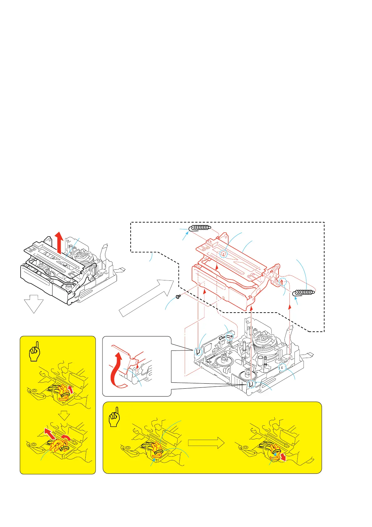
3-3. Cassette Compartment Assy
1. Removal procedure
1) Set the [EJ] mode.
2) Press the cassette compartment down halfway. Pull the cassette
compartment damper 1 in the direction of the arrow A. Then
rotate it in the B direction, and remove it in the direction of
C.
3) Remove the two screws (special head screw M1.4 × 1.4) 2.
4) Remove the LS chassis block assy 3 in the direction of the
arrow D.
5) Remove the pin E and groove F of the cassette compartment
assy 4 from the LS chassis groove G and pin H. Then remove
the cassette compartment block assy 4.
6) Remove the tension spring (POP UP T) (black) 5.
7) Remove the tension spring (POP UP S) (silver) 6.Then remove
the cassette compartment assy 7.
2. Attachment procedure
1) Set the [ULE] mode.
2) Install the tension spring (cassette compartment S) (POP UP
S) (silver) 6 in to the cassette compartment assy 7. (The
spring should be hooked on the front stay with the spring end
facing upward.)
3) Install the tension spring (cassette compartment T) (POP UP
T) (black) 5 in to the cassette compartment assy 7. (The
spring should be hooked on the front stay with the spring end
facing upward.)
4) Install the pin E and groove F of the cassette compartment
assy 4 into the LS chassis groove G and pin H.
5) In the status that the LS block assy 3 is kept open, insert it
into the grooves I and J of the LS chassis block assy.
6) Close the LS chassis block assy 3 in the direction opposite to
the arrow D, and install it with the two screws (special head
screw M1.4 × 1.4) 2.
Tightening torque: 0.059 ± 0.01N•m (0.6 ± 0.1kgf•cm)
7) The cassette compartment down halfway. Pass the K portion
of the cassette compartment damper 1 through the groove at
the tip of the cassette compartment. Then pull the L portion
and fix it using tweezers or something.
A
K
L
B
C
D
Cassette compartment
assy
REMOVING THE CASSETTE
COMPARTMENT DAMPER
7
Cassette compartment assy
6
Extension spring
(pop up S) (silver)
5
Extension spring
(pop up T) (black)
1
Cassette
compartment damper
3
LS frame
Pin
E
Pin
H
1
Cassette
compartment damper
2
Two screws
(M1.4
×
1.4)
4
Cassette
compartment
block assy
Groove
F
Groove
J
Tip groove of cassette
compartment assy
Groove
G
Groove
I
Key Points in Re-assembling
Points
to be noted
The spring hook
faces downward
The spring
hook faces
downward
 Loading...