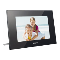
DPF-D710/D720/D810/D820/D1010/D1020
– 5 –
NOTE:
• -XX, -X mean standardized parts, so they may
have some differences from the original one.
• Items marked “*” are not stocked since they
are seldom required for routine service. Some
delay should be anticipated when ordering these
items.
• The mechanical parts with no reference number
in the exploded views are not supplied.
SECTION 1
EXPLODED VIEWS
ns: not supplied
The components identified by mark 0
or dotted line with mark 0 are critical for
safety.
Replace only with part number specified.
Les composants identifiés par une marque
0 sont critiques pour la sécurité.
Ne les remplacer que par une pièce portant
le numéro spécifié.
0
印の部品,または
0
印付の点線で囲ま
れた部品は,安全性を維持するために,
重要な部品です。
従って交換時は,必ず指定の部品を使用
してください。
1-1. OVERALL SECTION
• Color Indication of Appearance Parts
Example:
(BLACK) : Cabinet’s Color
(Black) : Parts Color
• Abbreviation
AR : Argentine model J : Japanese model
AUS : Australian model JE : Tourist model
BR : Brazilian model KR : Korea model
CH : Chinese model RUS : Russian model
CND : Canadian model TW : Taiwan model
EE : East European model
Ref. No. Part No. Description
Ref. No. Part No. Description
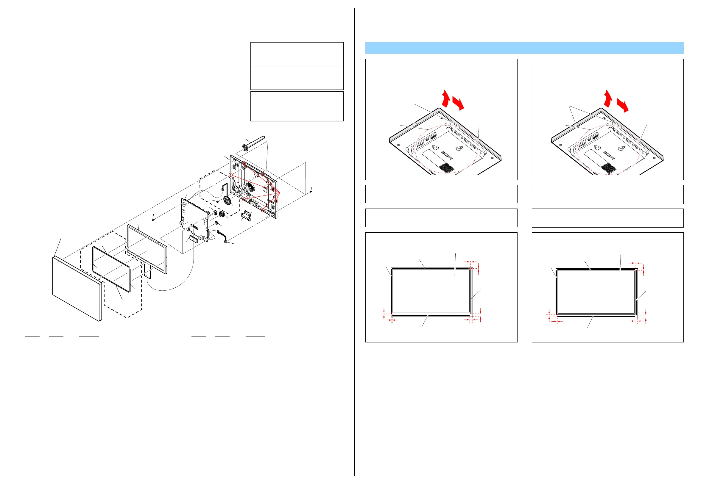
1 A-1797-774-A FRONT COVER ASSY (D710) (Note1, 2)
1 A-1797-777-A FRONT COVER ASSY (D720: BLACK) (Note1, 2)
1 A-1797-778-A FRONT COVER ASSY (WHITE) (Note1, 2)
1 A-1797-779-A FRONT COVER ASSY (RED) (Note1, 2)
1 A-1797-780-A FRONT COVER ASSY (BI) (CRYSTAL & BLACK)
(Note1, 2, 3)
1 A-1797-781-A FRONT COVER ASSY (BU) (CRYSTAL & BLACK)
(Note1, 2, 3)
1 A-1797-782-A FRONT COVER ASSY (BQ) (CRYSTAL & BLACK)
(Note1, 2, 3)
1 A-1797-783-A FRONT COVER ASSY (WI) (CRYSTAL & WHITE)
(Note1, 2)
2 4-262-599-01 SPONGE S, 7INCH (D720) (Note4)
3 4-262-596-01 SPONGE L, 7INCH (D720) (Note4)
0 4 1-811-302-11 LCD MODULE
5 3-042-244-11 SCREW, S (WHITE, CRYSTAL & WHITE)
5 3-080-206-11 SCREW, TAPPING, P2
(EXCEPT WHITE, CRYSTAL & WHITE)
0 6 A-1797-789-A MAIN PWB ASSY (D710)
0 6 A-1797-790-A MAIN PWB ASSY (D720)
7 4-141-818-01 SERVICE DC JACK
8 4-264-461-01 SCREW, SPEAKER (D720)
0 9 A-1797-797-A SPEAKER ASSY (D720)
10 A-1797-800-A REAR COVER ASSY (D710: EXCEPT J)
10 A-1797-801-A REAR COVER ASSY (D720: EXCEPT J
(WHITE, CRYSTAL & WHITE))
10 A-1797-802-A REAR COVER ASSY (D710: J)
10 A-1797-803-A REAR COVER ASSY (D720: J
(WHITE, CRYSTAL & WHITE))
10 A-1798-024-A REAR COVER ASSY (D720: EXCEPT J (BLACK, RED,
CRYSTAL & BLACK)
10 A-1798-025-A REAR COVER ASSY (D720: J (BLACK, RED,
CRYSTAL & BLACK))
11 4-209-592-01 STAND (D710/D720 (EXCEPT WHITE,
CRYSTAL & WHITE))
11 4-209-592-11 STAND (D720: WHITE, CRYSTAL & WHITE)
12 1-842-517-11 CONNECTOR, USB (SOCKET)
13 1-842-518-11 CONNECTOR, USB (SOCKET)
14 A-1797-799-A IR LENS
DPF-D710/D720
Note
Note3: Refer to “How to Distinguish the Front Cover Service of
Crystal Model” on page 8 when you exchange the front cover
service of crystal model.
Note2: Open the Rear Cover Assy by putting it down, since the LCD
Module is not fixed and the flexible board or cable is too
short.
Note3:
クリスタルモデルのフロントカバー ASSYを交換する場合,
8ページの“How to DistinguishtheFrontCoverServiceof
CrystalModel”を参照してください。
Note2:
LCDモジュールが固定されておらず,フレキシブルボードや
ケーブルが短いため,フロントカバー ASSYを開けるときは,
リアカバー ASSYを下にして開いてください。
Note1: When removing the Front Cover Assy, draw the corner of
the Front Cover Assy in the direction shown by arrow
1
while holding the box part of the Rear Cover Assy, then open
from the upper edge of the Front Cover Assy in the direction
shown by arrow
2
.
Note1:
フロントカバー ASSYの取り外しは,リアカバー ASSYのボック
ス部をつかみながらフロントカバー ASSYの角を矢印①の方向
へ引き,本体上面を矢印②の方向へ順に開いてください。
Front Cover Assy
Claw
Box part
1
2
フロントカバーASSY
ツメ
ボックス部
1
2
1
(Note1, 2, 3)
(Note4)
3
3
(Note4)
2
(Note4)
(Note4)
2
4
5
6
8
12
10
11
5
9
7
13
14
ns
ns
D720
D720
Claw
Note4:
LCDモジュールの下図の位置にスポンジを貼り付けてくださ
い。
0〜12.9mm
0〜10mm
0〜3.5mm
0〜1.4mm
0〜4.5mm
0〜0.9mm
スポンジS 7インチ
スポンジS 7インチ
スポンジL 7インチ
スポンジL 7インチ
LCDモジュール
Note4: Attach the sponge to the LCD Module on the position as
shown in the figure below.
0 to 12.9mm
0 to 10mm
0 to 3.5mm
0 to 1.4mm
0 to 4.5mm
0 to 0.9mm
SPONGE S, 7INCH
SPONGE S, 7INCH
SPONGE L, 7INCH
SPONGE L, 7INCH
LCD MODULE


 To Next Page
 Loading...