DPF-D710/D720/D810/D820/D1010/D1020
– 6 –
Ref. No. Part No. Description
Ref. No. Part No. Description
1 A-1797-775-A FRONT COVER ASSY (D810) (Note1, 2)
1 A-1797-784-A FRONT COVER ASSY (D820: BLACK) (Note1, 2)
1 A-1797-785-A FRONT COVER ASSY (WHITE) (Note1, 2)
2 4-262-600-01 SPONGE S, 8INCH (D820) (Note3)
3 4-262-597-01 SPONGE L, 8INCH (D820) (Note3)
0 4 1-811-303-11 LCD MODULE
5 A-1797-798-A LOGO LIGHT PIPE ASSY (D810)
5 A-1798-023-A LOGO LIGHT PIPE ASSY (D820)
6 3-080-206-21 SCREW, TAPPING, P2 (D810 / D820: BLACK)
6 7-685-103-14 SCREW +P 2X5 TYPE2 NON-SLIT (WHITE)
0 7 A-1797-792-A MAIN PWB ASSY (D810)
0 7 A-1797-793-A MAIN PWB ASSY (D820)
8 4-264-461-01 SCREW, SPEAKER (D820)
0 9 A-1797-797-A SPEAKER ASSY (D820)
10 A-1797-804-A REAR COVER ASSY (D810)
10 A-1798-026-A REAR COVER ASSY (D820: BLACK)
10 A-1797-805-A REAR COVER ASSY (WHITE)
11 4-258-236-01 STAND (D810 / D820: BLACK)
11 4-258-236-11 STAND (WHITE)
12 4-141-818-01 SERVICE DC JACK
13 1-842-517-11 CONNECTOR, USB (SOCKET)
14 1-842-518-11 CONNECTOR, USB (SOCKET)
15 A-1797-799-A IR LENS
DPF-D810/D820
Note
The components identified by mark 0 or
dotted line with mark 0 are critical for safety.
Replace only with part number specified.
Les composants identifiés par une marque
0 sont critiques pour la sécurité.
Ne les remplacer que par une pièce portant
le numéro spécifié.
0
印の部品,または
0
印付の点線で囲ま
れた部品は,安全性を維持するために,
重要な部品です。
従って交換時は,必ず指定の部品を使用
してください。
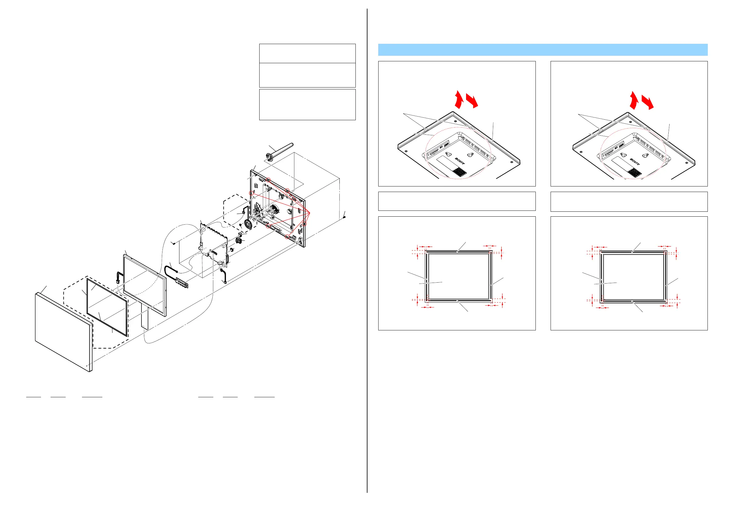
Note1:
フロントカバー ASSYの取り外しは,リアカバー ASSYのボック
ス部をつかみながらフロントカバー ASSYの角を矢印①の方向
へ引き,本体上面を矢印②の方向へ順に開いてください。
Note1: When removing the Front Cover Assy, draw the corner of
the Front Cover Assy in the direction shown by arrow
1
while holding the box part of the Rear Cover Assy, then open
from the upper edge of the Front Cover Assy in the direction
shown by arrow
2
.
Note2: Open the Rear Cover Assy by putting it down, since the LCD
Module is not fixed and the flexible board or cable is too
short.
Note2:
LCDモジュールが固定されておらず,フレキシブルボードや
ケーブルが短いため,フロントカバー ASSYを開けるときは,
リアカバー ASSYを下にして開いてください。
Front Cover Assy
Claw
Box part
1
2
フロントカバーASSY
ツメ
ボックス部
1
2
Claw
(Note1, 2)
1
2
(Note3)
2
(Note3)
3(Note3)
3(Note3)
4
5
6
7
9
8
12
13
14
10
11
6
15
D820
D820
Note3:
LCDモジュールの下図の位置にスポンジを貼り付けてくださ
い。
Note3: Attach the sponge to the LCD Module on the position as
shown in the figure below.
0 to 12mm
0 to 12mm
0 to 10mm
0 to 10mm
0 to 5.2mm
0 to 6mm
0 to 6mm
0 to 5.2mm
SPONGE S,
8INCH
SPONGE L, 8INCH
SPONGE S,
8INCH
SPONGE L, 8INCH
LCD MODULE
0〜12mm
0〜12mm
0〜10mm
0〜10mm
0〜5.2mm
0〜6mm
0〜6mm
0〜5.2mm
スポンジS
8インチ
スポンジS
8インチ
スポンジL 8インチ
スポンジL 8インチ
LCDモジュール