DSC-RX10_L2
2-8
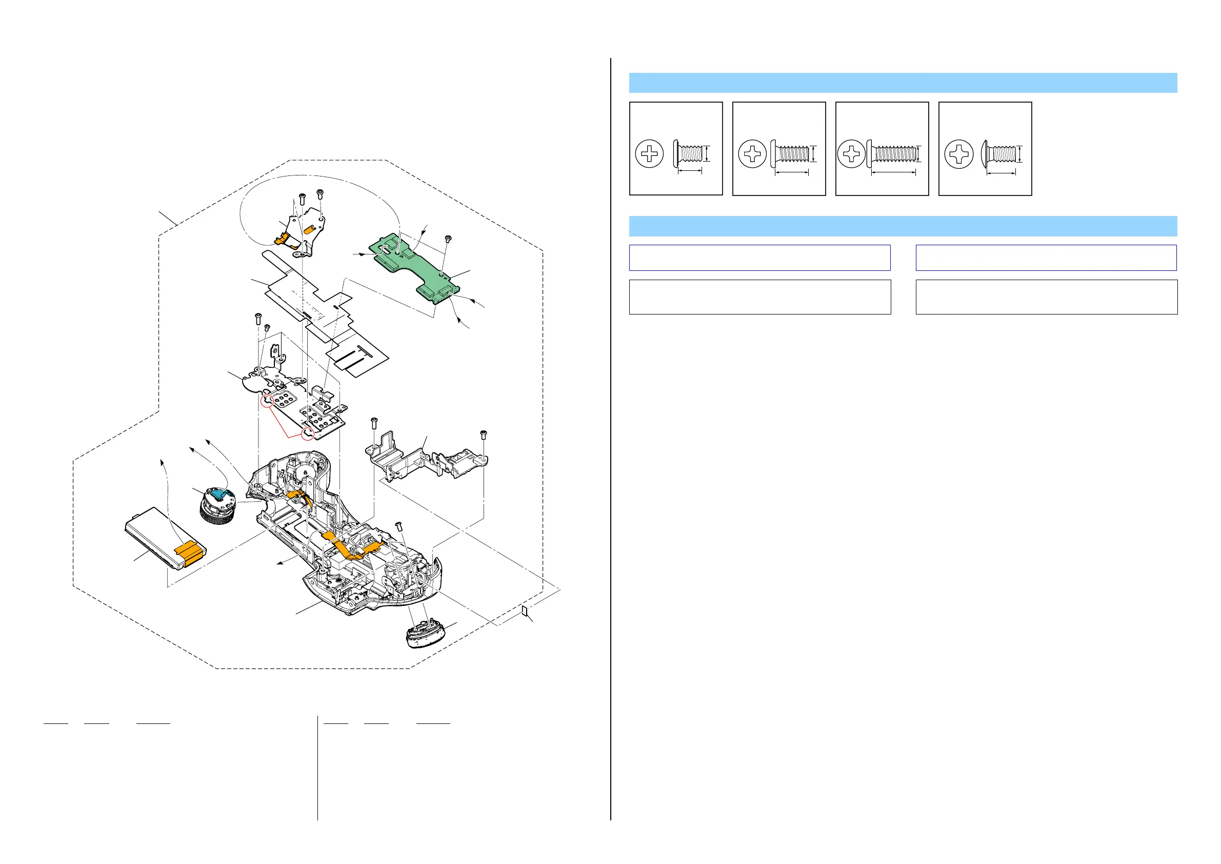
2-1-5. UPPER CABINET SECTION
ns : not supplied
Ref. No. Part No. Description
Ref. No. Part No. Description
201 A-1973-243-A DIAL, MODE BLOCK ASSY
202 1-492-593-11 SWITCH BLOCK, CONTROL (EV63720)
203 A-1973-075-A TP-1001 BOARD, COMPLETE
* 204 4-528-670-01 SHEET (DROP PROTECTION A) (Note 1)
205 A-1992-172-A RL-1026 FLEXIBLE BOARD, COMPLETE (SERVICE)
(Note 2)
206 4-488-193-01 SHEET (VF), ADHESIVE
207 A-1992-170-A CABINET UPPER BLOCK (SERVICE)
LCD903 A-1992-174-A MODULE BLOCK ASSY (SERVICE)
#1 2-635-562-11 SCREW (M1.7)
#5 3-080-204-01 SCREW, TAPPING, P2
#12 3-080-204-21 SCREW, TAPPING, P2
#26 2-635-591-11 SCREW (M1.4), NEW TRUSTAR P2
Note
Note 1: Refer to “Assembly-5: Notes on assembling the Sheet (Drop
Protection A)” when assembling.
Note 1: 組立時は““Assembly-5: Notes on assembling the Sheet (Drop
Protection A)”を参照してください。
(Hooks)
A
A
B
B
C
C
D
D
ns
ns
ST Block Section
(See page 2-9)
#12
(Note 1)
#12
#12
#12
#1
#5
#5
#26
202
204
207
201
206
205
(Note 2)
203
LCD903
Screw
#1: M1.7 X 2.5
(Black)
2-635-562-11
2.5
1.7
#5: M1.7 X 3.5 (Tapping)
(Black)
3-080-204-01
3.5
1.7
#12: M1.7 X 5.0 (Tapping)
(Black)
3-080-204-21
1.7
5.0
#26: M1.4 X 2.0
(Silver)
2-635-591-11
2.0
1.4
Note 2: When this part is removed, adjustment is required.
For the adjustment method, refer to “Adjustment items after
replacing parts” in the Note tab of the Adjust manual.
Note 2:
この部品を取り外したときは調整が必要です。
調整方法についてはAdjust manual の Noteタブにある
Adjustment items after replacing parts を参照してください。
 Loading...