Getting Started
8
Getting Started
DST-HD500 2-663-710-11(2)
ANT.
VIDEO OUTPUT RS-232
RF OUT
S-VIDEO
CVBS
COAX.
L
R
L
R
OPTICAL
Y
P
b
Pr
Y
P
b
Pr
RF IN
RF IN
AUDIO OUTPUT
DIGITAL ANALOG
L
R
HD IN
1
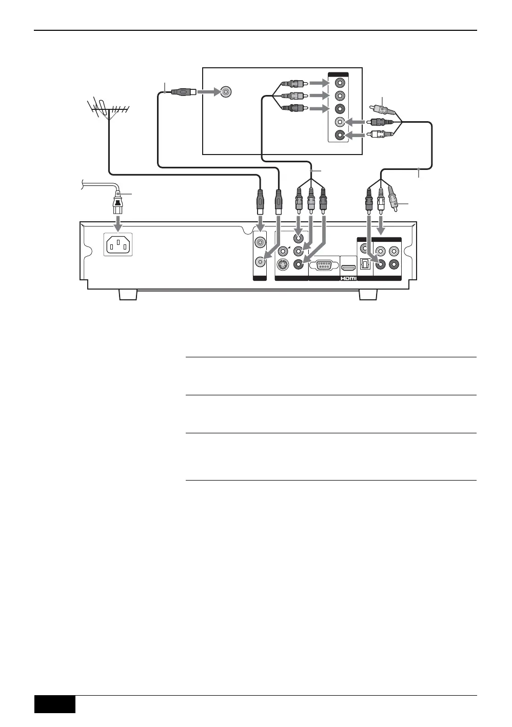
Connect your aerial cable to the socket labelled RF IN on the
rear of the receiver.
2
Connect the supplied RF cable from the socket labelled RF
OUT on the rear of the receiver to the aerial socket on your
TV/display screen.
3
Connect the supplied Y/Pb/Pr cable from the sockets labelled
Y, PB and PR on the rear of the receiver to the component input
sockets on your TV/display screen.
4
Connect the supplied AV cable from the sockets labelled L, and
R on the rear of the receiver to the audio input sockets on your
TV/display screen. (The yellow video jack does not need to be
connected.)
5
Connect the supplied AC cord from the AC IN socket on the
rear of the receiver to your mains socket (100 - 240V AC,
50/60Hz).
Connecting to an HD TV/display screen via Component output
Rear of TV/display screen
Y/Pb/Pr
cable
(supplied)
AV cable (supplied)
Video jack
(not required)
Video jack
(not required)
RF cable (supplied)
AC Cord
(supplied)
To m ains
DST-HD100A.book Page 8 Saturday, September 17, 2005 5:36 AM



 To Next Page