 Loading...
Do you have a question about the Sony DSX-A50BT and is the answer not in the manual?
| MP3 playback | Yes |
|---|---|
| CD-R playback | No |
| FM band range | 87.5 - 108 MHz |
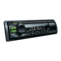
| Product color | Black |
| Amplifier output power | 50 W |
| Weight | 700 g |
|---|---|
| Dimensions (WxDxH) | 178 x 120 x 50 mm |