Do you have a question about the Sony DTC-A8 and is the answer not in the manual?
Details about tape, head, recording time, speed, drum rotation, and error correction.
Power requirements, consumption, dimensions, and weight for the unit and remote.
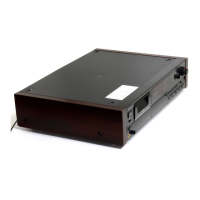
Specifies the location of the model number label on the unit.
Procedures for testing AC leakage from exposed metal parts to earth ground.
Instructions for setting the unit's internal clock for date/time recording.
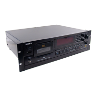
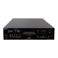
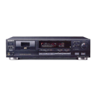
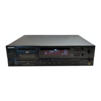
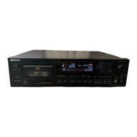
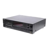
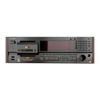
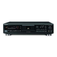
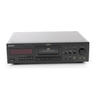
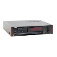
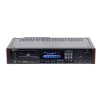
Identifies the main section and remote commander components.
Procedure for removing the outer case of the unit.
Procedure for removing the cassette holder assembly.
Procedure for removing the front panel assembly.
Procedure for removing the back panel assembly.
Procedure for removing digital and audio boards.
Procedure for removing mechanism deck and power transformer.
Procedures for mechanical adjustments, including tape pass and guide settings.
Procedures for electrical adjustments like end sensor, torque, and tape pass fine tuning.
Detailed pin descriptions for various ICs used in the unit.
Block diagram illustrating the audio signal path and components.
Diagrams showing the physical location of circuit boards within the unit.
Printed wiring board layout for the RF section.
Schematic diagram for the RF section.
Printed wiring board layout for the digital section.
Schematic diagram for the audio section.
Functional block diagrams for key integrated circuits.
Exploded view and parts list for the main chassis assembly.
Exploded view and parts list for the front panel components.
Exploded view and parts list for the cassette compartment.
Exploded view and parts list for mechanism deck components.
Exploded view and parts list for mechanism deck components.
Exploded view and parts list for mechanism deck components.
Lists included accessories, packing materials, and hardware items.
| Sampling Frequency | 48 kHz, 44.1 kHz, 32 kHz |
|---|---|
| Power Consumption | 25 W |
| Type | DAT (Digital Audio Tape) Deck |
| Recording Time | Up to 120 minutes |
| Frequency Response | 2 Hz to 22 kHz (48 kHz sampling) |
| Signal-to-Noise Ratio | > 92 dB |
| Dynamic Range | > 92 dB |
| Digital Inputs | 1 x Coaxial, 1 x Optical |
| Digital Outputs | 1 x Coaxial, 1 x Optical |
| Analog Inputs | 1 x RCA |
| Analog Outputs | RCA (Line) |
| Dimensions | 430 x 110 x 350 mm (W x H x D) |
| Tape Speed | 8.15 mm/sec |