EasyManua.ls Logo

Sony DVP-CX777ES Service Manual

Sony DVP-CX777ES
154 pages
To Next Page IconTo Next Page
Page #1 background imageLoading...
Page #1 background image
SERVICE MANUAL
CD/DVD PLAYER
US Model
Canadian Model
SPECIFICATIONS
DVP-CX777ES
Ver 1.1 2004.09
9-961-043-02 Sony Corporation
2004I05-1 Audio Group
C 2004.09 Published by Sony Engineering Corporation
Model Name Using Similar Mechanism NEW
CD/DVD Mechanism Type CDM62-DVBU26
Base Unit Name DVBU26
Optical Pick-up Name KHM-290AAA
System
Laser: Semiconductor laser
λ = 780 nm for CD
λ = 650 nm for SA-CD and DVD
Emission duration: continuous
Signal format system: NTSC
Audio characteristics
Frequency response: DVD VIDEO (PCM
96 kHz): 2 Hz to 44 kHz (44 kHz: –2 dB
±1 dB), Super Audio CD: 2 Hz to
100 kHz (50kHz:3dB ±1 dB), CD:
2Hz to 20 kHz (±0.5 dB)
Signal-to-noise ratio (S/N ratio): 115 dB
(LINE OUT AUDIO L/R 1/2 jacks only)
Harmonic distortion: 0.003 %
Dynamic range: DVD VIDEO/Super Audio
CD: 103 dB, CD: 99 dB
Wow and flutter: Less than detected value
(±0.001% W PEAK)
Outputs
(Jack name: Jack type/Output level/Load
impedance)
LINE OUT AUDIO L/R 1/2: Phono jack/
2Vrms/10kilohms
DIGITAL OUT (OPTICAL): Optical
output jack/–18 dBm (wave length:
660 nm)
DIGITAL OUT (COAXIAL): Phono jack/
0.5 Vp-p/75 ohms
5.1CH OUTPUT: Phono jack/2 Vrms/
10 kilohms
COMPONENT VIDEO OUT (Y, P
B
/C
B
,
P
R
/C
R
): Phono jack/Y: 1.0 Vp-p/P
B
/C
B
,
P
R
/C
R
: interlace*=0.648 Vp-p,
progressive or interlace**=0.7 Vp-p/
75 ohms
*BLACK LEVEL is ON
** BLACK LEVEL is OFF
LINE OUT VIDEO 1/2: Phono jack/
1.0 Vp-p/75 ohms
S VIDEO OUPUT 1/2: 4-pin mini DIN/
Y: 1.0 Vp-p/C: 0.286 Vp-p /75 ohms
S-LINK (CONTROL S IN): Mini jack
General
Power requirements:
120 V AC, 60 Hz
Power consumption: 24 W
Dimensions (approx.): 430 × 189 × 545 mm
(17 × 7
1
/
2
× 21
1
/
2
in.) (width/height/
depth) incl. projecting parts
Mass (approx.): 10 kg (22 lb 1 oz)
Operating temperature: 5 ° C to 35 °C
(41
°
F to 95
°
F)
Operating humidity: 25 % to 80 %
Supplied accessories
Specifications and design are subject to
change without notice.
•Audio/video cord (pinplug × 3 y pinplug
•Remote commander (remote) (1)
•Size AA (R6) batteries (2)
× 3) (1)
E
NERGY
S
TAR
R
is a U.S. registered mark.
As an
E
NERGY
S
TAR
R
Partner, Sony
Corporation has determined that this product
meets the
E
NERGY
S
TAR
R
guidelines for
energy efficiency.

Table of Contents

Other manuals for Sony DVP-CX777ES

Question and Answer IconNeed help?

Do you have a question about the Sony DVP-CX777ES and is the answer not in the manual?

Sony DVP-CX777ES Specifications

General IconGeneral
TypeDVD Player
Video OutputComposite, S-Video, Component
Audio D/A Converter192 kHz/24-bit
Progressive ScanYes
Remote ControlYes
Output Resolution480i, 480p
Audio OutputCoaxial, Optical
Audio Formats SupportedDolby Digital, DTS
Playback FormatsDVD, CD
Video D/A Converter108MHz/12-bit

Summary

Service Manual

Specifications Overview

Details on system, audio characteristics, outputs, and general specifications.

Self-Diagnosis Function

Unleaded Solder Information

Notes on Chip Component Replacement

Precautions for replacing chip components, especially tantalum capacitors.

Flexible Circuit Board Repairing

Guidelines for soldering and handling flexible circuit boards during repair.

Safety Check-out and Leakage Test

Procedures for performing AC leakage tests after repairs.

Disc Playability Information

Discs Supported by the Player

Lists the types of discs the player can read and play.

Region Code Restrictions

Explanation of the DVD region code system and playback limitations.

Discs the Player Cannot Play

Details incompatible disc formats and conditions.

Playback Operations Notes

Notes on specific playback operations for DVDs and Video CDs.

Section 1 Servicing Notes

Handling Optical Pick-up Block

Precautions for handling the optical pick-up block and flexible boards.

Laser Diode Emission Check

Procedure for safely checking the laser diode emission.

MB Board Replacement Procedure

Steps to initialize memory after replacing the MB board.

Power Board Check Procedure

Method to check power board voltages with the unit powered on.

Alignment of Gear Phase

Cleaning the Optical Pick-up

Instructions for cleaning the lens of the optical pick-up.

Note for Installation

Important tip regarding cable routing during installation.

Service Position Guidance

MB Board Service Position

Connecting the jig to the MB board for service.

Optical Pick-up Block Service Position

Service points for the optical pick-up block.

Section 2 General Overview

Front Panel Controls and Indicators

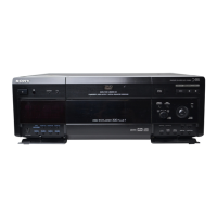
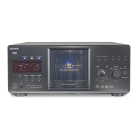
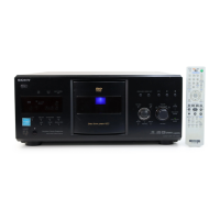
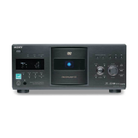
Description of controls and indicators on the front panel.

Rear Panel Connections

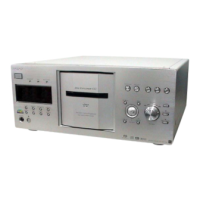
Description of all connectors and ports on the rear panel.

Remote Commander Functions

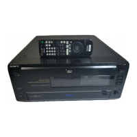
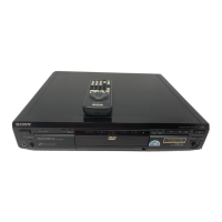
Detailed explanation of buttons and functions on the remote control.

Section 3 Disassembly Procedures

Disassembly Flow Chart

Step-by-step process for disassembling the unit.

Case (ES) Assy Disassembly

Procedure for removing the outer case assembly.

MB Board Removal

Steps to remove the main board (MB).

AV Board Removal

Procedure for removing the AV board.

Bracket (L)/(R) Removal

Steps for removing the left and right brackets.

Front Panel Section Disassembly

Procedure for disassembling the front panel components.

Cover (PT)/(CDM) Removal

Steps to remove the PT and CDM covers.

DVBU26 Assy Removal

Procedure for removing the DVBU26 assembly.

Power Block and Transformer Removal

Steps to remove the power block and transformer (T102).

Table (400) Assy Disassembly

Procedure for disassembling the table assembly.

Door Block, Base (Door) Assy Disassembly

Steps to remove the door block and base assembly.

DC Motor (Door) Removal

Procedure for removing the DC motor for the door.

Holder (Table Sensor 400) Removal

Steps to remove the table sensor holder.

D. SENS Boards Removal

Procedure for removing the D. SENS OUT and IN boards.

Pop-up (400) Assy Removal

Steps to remove the pop-up assembly.

Door SW Board Removal

Procedure for removing the door switch board.

Lock SW and Loading SW Boards Removal

Steps to remove the lock and loading switch boards.

CD/DVD Mechanism Deck Block Removal

Procedure for removing the CD/DVD mechanism deck block.

Motor Assembly and Loading Motor Board Removal

Steps to remove motor assemblies and the loading motor board.

Optical Pick-up Removal

Procedure for removing the optical pick-up unit.

Section 4 Test Mode Operations

General Description of Test Mode

Overview of the test mode for diagnosis and adjustment.

Starting the Test Mode

Procedure to activate the test mode using the remote commander.

Syscon Diagnosis Function

Details on performing system controller diagnosis.

Checking Method Descriptions

Version and Revision Check

Checking the firmware version and revision number.

Peripheral Component Checks

Procedures for checking EEPROM, Gate Array, and NAND Flash.

Servo and Data System Checks

Servo System Checks

Details on checking Servo DSP and RF Amp.

Data Supply System Checks

Procedures for checking ARP registers and RAM.

AV Decoder and Video Output Checks

AV Decoder Checks

Procedures for checking 1935 RAM and 1935 SP.

Video Output Signal Checks

Checking Color Bar, Composite, Y/C, and Component outputs.

Audio Output Checks

Procedures for checking ARP to 1935, Audy, and Test Tone.

Drive Auto Adjustment Procedures

DVD Single Layer Disc Adjustment

Steps for adjusting DVD single layer discs.

CD Disc Adjustment

Steps for adjusting CD discs.

DVD Dual Layer Disc Adjustment

Steps for adjusting DVD dual layer discs.

LCD Adjustment

Notes on LCD disc adjustment.

Drive Manual Operation

Drive Manual Operation Menu

Overview of the manual operation menu options.

Disc Check Memory and Disc Type Setting

Procedures for checking discs and setting disc type.

Servo Control Adjustments

On/off control and adjustments for servo systems.

Track/Layer Jump Operations

Performing track and layer jumps for DVD-DL discs.

Manual Adjustment of Parameters

Manually adjusting various parameters like TRK offset and focus gain.

Auto Adjustment Procedures

Auto Adjustment of Parameters

Automatically adjusting tracking offset, focus balance, and other parameters.

EEPROM Memory Check

Displaying current servo adjusted data stored in EEPROM.

Changer Mechanism Operations

Changer Manual Move Operations

Manual operation of the disc loading and table movement.

Changer Mecha Check Procedures

Checking table sensors and disc sensors.

Test Mode Functions

Mecha Aging Status

Information on mechanism aging support.

Emergency History Log

Displaying and clearing emergency history and laser hours.

Version Information Display

Checking ROM version, region code, and other system details.

Video Level Adjustment

Procedure for adjusting video levels using color bars.

IF CON Self-Diagnostic Function

Panel-L Board (IF CON) Test Mode

Test mode for diagnosing IF CON functions on the Panel-L board.

Self Check Mode Operation

Function to perform basic tests on the FL display and panel section.

IF CON Information Display

Displaying IF CON status including model and version.

FL Tube Grid and Segment Check

Test for the FL display grid and segment patterns.

SIRCS Reception Check

Checking the reception of SIRCS remote control signals.

Key Input Checks

Checking the functionality of all front panel keys.

JOG Dial and LED Check

Testing the JOG dial rotation and LED indicator responses.

Keyboard Input Check

Verifying signals received from the keyboard.

CIS Check Procedure

Method for conducting the CIS check.

Self Check Mode Completion

Displaying the completion status of the self-check mode.

Section 4 Troubleshooting

Cannot Enter Test Mode

Troubleshooting steps when the test mode cannot be entered.

Test Mode Menu Not Displayed (MB Board)

Troubleshooting steps for MB board issues preventing test mode display.

Troubleshooting Test Mode Issues

33 MHz Signal Appearance at CPUCK

Troubleshooting when 33 MHz signal appears at CPUCK.

Test Mode Menu Displayed, Machine Stops

Troubleshooting steps when machine stops after menu selection.

SDSP No Ack Message

Troubleshooting the "SDSP No Ack" message.

Diag All Check Item Troubles

Troubleshooting issues occurring in the 'Diag All Check'.

No Picture or Audio Output

Troubleshooting steps when no picture or audio is output.

Picture Output, No Audio

Troubleshooting steps when audio is not output, but picture is.

Audio Output, No Picture

Troubleshooting steps when picture is not output, but audio is.

Drive Auto Adjustment Errors

Troubleshooting drive auto adjustment failures.

Troubleshooting Product or Component Defects

FL Display Not Lighting

Troubleshooting steps when the FL display does not light.

FL Display Lights Briefly Then Off

Troubleshooting FL display behavior after power button press.

No Picture and Audio Output

Troubleshooting when both picture and audio are missing.

Abnormal Picture Display

Troubleshooting issues like block noise or abnormal picture.

Section 5 Mechanical Adjustments

Pop-up Mechanism Adjustment

Procedure for adjusting the pop-up mechanism.

Table Sensor Adjustment

Procedure for adjusting the table sensor.

Section 6 Electrical Adjustments

Auto Servo Adjustment Procedure

Re-adjusting the servo circuit after component replacement.

Power Supply Check

Checking voltages on the power board against specifications.

Video System Adjustments

Video Level Adjustment (MB Board)

Adjusting video output level for NTSC standard compliance.

Progressive Video Output Level Adjustment

Adjusting progressive video output for correct brightness.

S Video Output S-Y Check

Checking S-terminal video output for correct pictures.

S Video Output S-C Check

Checking S-C output against NTSC standard for color accuracy.

Component Video Output Checks

Component Video Output Y Check

Checking the Y component for correct brightness.

Component Video Output B-Y Check

Checking the B-Y component for correct colors.

Component Video Output R-Y Check

Checking the R-Y component for correct colors.

Disc Detect Sensor Adjustment

Section 7 Diagrams

Block Diagram - RF Section

Schematic block diagram of the RF signal path.

Block Diagram - Servo/Changer Section

Block diagram of the servo and changer mechanisms.

Block Diagram - Audio Section

Block diagram illustrating the audio signal processing.

Block Diagram - Video Section

Block diagram showing the video signal path.

Block Diagram - Panel/Power Supply Section

Block diagram of the panel and power supply circuitry.

Notes on Printed Wiring Boards and Schematics

Guidelines for interpreting diagrams and wiring boards.

Circuit Board Locations

Schematic Diagram - MB Board (1/15)

Schematic Diagram - MB Board (2/15)

Schematic Diagram - MB Board (3/15)

Schematic Diagram - MB Board (4/15)

Schematic Diagram - MB Board (5/15)

Schematic Diagram - MB Board (6/15)

Schematic Diagram - MB Board (7/15)

Schematic Diagram - MB Board (8/15)

Schematic Diagram - MB Board (9/15)

Schematic Diagram - MB Board (10/15)

Schematic Diagram - MB Board (11/15)

Schematic Diagram - MB Board (12/15)

Schematic Diagram - MB Board (13/15)

Schematic Diagram - MB Board (14/15)

Schematic Diagram - MB Board (15/15)

Printed Wiring Board - MB Board (Component Side)

Printed Wiring Board - MB Board (Conductor Side)

Printed Wiring Board - Driver Board

Schematic Diagram - Driver Board

Printed Wiring Boards - Motor/Switch Section

Schematic Diagram - Motor/Switch Section

Printed Wiring Boards - Sensor Section

Schematic Diagram - Sensor Section

Printed Wiring Board - AV Board (Component Side)

Printed Wiring Board - AV Board (Conductor Side)

Printed Wiring Board - RS-232C Board

Schematic Diagram - AV (1/3)/RS-232C Boards

Schematic Diagram - AV Board (2/3)

Schematic Diagram - AV Board (3/3)

Printed Wiring Board - Panel-L Board (Component Side)

Printed Wiring Board - Panel-L Board (Conductor Side)

Schematic Diagram - Panel-L Board (1/2)

Schematic Diagram - Panel-L Board (2/2)

Printed Wiring Boards - Panel Section

Schematic Diagram - Panel Section

Printed Wiring Board - Power Board

Schematic Diagram - Power Board

Signal Waveforms

MB Board Waveforms

Signal waveforms for various points on the MB board.

AV Board Waveforms

Signal waveforms for various points on the AV board.

Panel-L Board Waveforms

Signal waveforms for various points on the Panel-L board.

IC Block Diagrams

MB Board IC Block Diagrams

Block diagrams for ICs on the MB board.

AV Board IC Block Diagrams

Block diagrams for ICs on the AV board.

Driver Board IC Block Diagrams

Block diagrams for ICs on the driver board.

Panel-L Board IC Block Diagrams

Block diagrams for ICs on the Panel-L board.

IC Pin Function Descriptions

MB Board IC104 Pin Functions

Detailed pin functions for the System Controller (IC104).

MB Board IC201 Pin Functions

Detailed pin functions for the RF AMP (IC201).

MB Board IC301 Pin Functions

Detailed pin functions for the DSP/Servo Processor (IC301).

MB Board IC403 Pin Functions

Detailed pin functions for the AV Decoder (IC403).

MB Board IC501 Pin Functions

Detailed pin functions for the Audio DSP (IC501).

MB Board IC602 Pin Functions

Detailed pin functions for the Video Converter (IC602).

MB Board IC701 Pin Functions

Detailed pin functions for the Mechanism Controller (IC701).

MB Board IC801 Pin Functions

Detailed pin functions for the Audio Processor (IC801).

MB Board IC905 Pin Functions

Detailed pin functions for the DSD Decoder (IC905).

Panel-L Board IC1003 Pin Functions

Detailed pin functions for the Interface Controller (IC1003).

Section 8 Exploded Views

Overall Section Exploded View

Exploded view of the entire unit assembly.

Front Panel Section Exploded View

Exploded view of the front panel components.

Power Block Section Exploded View

Exploded view of the power block assembly.

Table Section Exploded View

Exploded view of the table mechanism components.

Chassis Section Exploded View

Exploded view of the main chassis and associated parts.

Base (Door) Section Exploded View

Exploded view of the base and door mechanism components.

Mechanism Deck Section-1 (Pop-up Block)

Exploded view of the pop-up block mechanism.

Mechanism Deck Section-2 (Pulley Block)

Exploded view of the pulley block mechanism.

Mechanism Deck Section-3 (Lever, Holder Block)

Exploded view of the lever and holder block mechanism.

Mechanism Deck Section-4 (Gear, Motor Block)

Exploded view of the gear and motor block mechanism.

Optical Pick-up Section (DVBU26) Exploded View

Exploded view of the optical pick-up assembly.

Section 9 Electrical Parts List (AV)

Revision History

Related product manuals