EasyManua.ls Logo

Sony DVP-CX995V Service Manual

Sony DVP-CX995V
116 pages
To Next Page IconTo Next Page
Page #1 background imageLoading...
Page #1 background image
SERVICE MANUAL
CD/DVD PLAYER
US Model
Canadian Model
DVP-CX995V
Ver. 1.1 2005.12
SPECIFICATIONS
9-879-772-02
2005L05-1
© 2005.12
Sony Corporation
Home Audio Division
Published by Sony Engineering Corporation
Model Name Using Similar Mechanism NEW
CD/DVD Mechanism Type CDM62-DVBU65
Base Unit Name DVBU65
Optical Traverse Unit Name DBU-3
* Manufactured under license from Dolby
Laboratories. “Dolby,” “Pro Logic,” and the
double-D symbol are trademarks of Dolby
Laboratories.
** “DTS” and “DTS Digital Surround” are
registered trademarks of Digital Theater
Systems, Inc.
System
Laser: Semiconductor laser
λ = 780 nm for CD
λ = 650 nm for Super Audio CD and
DVD
Emission duration: continuous
Signal format system: NTSC
Audio characteristics
Frequency response: DVD VIDEO (PCM
96 kHz): 2 Hz to 44 kHz (44 kHz: –2 dB
±1 dB), Super Audio CD: 2 Hz to
100 kHz (50 kHz: –3 dB ±1dB), CD:
2Hz to 20 kHz (±0.5 dB)
Signal-to-noise ratio (S/N ratio): 115 dB
(LINE OUT AUDIO L/R 1/2 jacks only)
Harmonic distortion: 0.003 %
Dynamic range: DVD VIDEO/Super Audio
CD: 103 dB, CD: 99 dB
Wow and flutter: Less than detected value
(±0.001% W PEAK)
Outputs
(Jack name: Jack type/Output level/Load
impedance)
LINE OUT AUDIO L/R 1/2: Phono jack/
2Vrms/10 kilohms
DIGITAL OUT (OPTICAL): Optical
output jack/–18 dBm (wave length:
660 nm)
DIGITAL OUT (COAXIAL): Phono jack/
0.5 Vp-p/75 ohms
HDMI OUTPUT: TypeA (19 pin)
5.1CH OUTPUT: Phono jack/2 Vrms/
10 kilohms
COMPONENT VIDEO OUT(Y, P
B/CB, PR/
C
R):
Phono jack/Y: 1.0 Vp-p/P
B/CB, PR/CR:
interlace
1)
= 0.648 Vp-p, progressive or
interlace
2)
= 0.7 Vp-p/75 ohms
1) BLACK LEVEL (COMPONENT
OUT) is ON
2) BLACK LEVEL (COMPONENT
OUT) is OFF
LINE OUT (VIDEO) 1/2: Phono jack/
1.0 Vp-p/75 ohms
S VIDEO OUT 1/2: 4-pin mini DIN/Y:
1.0 Vp-p, C: 0.286 Vp-p/75 ohms
General
Power requirements:
120 V AC, 60 Hz
Power consumption: 25 W
Dimensions (approx.): 430 × 189 × 545 mm
(17 × 7
1
/
2
× 21
1
/
2
in.) (width/height/depth)
incl. projecting parts
Mass (approx.): 8.6 kg (18 lb 15 oz)
Operating temperature: 5 °C to 35 °C
(41
°F to 95 °F)
Operating humidity: 25 % to 80 %
Supplied accessories
Audio/video cord
(pinplug × 3 y pinplug × 3) (1)
Specifications and design are subject to
change without notice.
Remote commander (remote) (1)
Size AA (R6) batteries (2)

Table of Contents

Other manuals for Sony DVP-CX995V

Question and Answer IconNeed help?

Do you have a question about the Sony DVP-CX995V and is the answer not in the manual?

Sony DVP-CX995V Specifications

General IconGeneral
Disc Capacity400 Discs
Video OutputComposite, S-Video, Component
Progressive ScanYes
Video Output SystemNTSC
Surround SoundDolby Digital, DTS
Remote ControlYes
UpscalingNo
Playable Disc TypesDVD, CD, MP3 CD, JPEG CD
Audio OutputDigital Audio Optical, Digital Audio Coaxial, Analog Audio

Summary

Service Manual Overview

Specifications

Detailed technical specifications for the CD/DVD player.

Servicing Notes and Precautions

Safety Check-out and Leakage Test

Procedure for testing AC leakage current from exposed metal parts.

Disassembly and Adjustments

Disassembly Flow

A flowchart outlining the sequence of disassembly steps.

Test Mode Operation

Instructions for entering and operating the test mode for diagnosis.

Mechanical Adjustments

Procedures for adjusting mechanical parts like the pop-up mechanism.

Electrical Adjustments

Procedures for adjusting electrical parameters, including video levels.

Diagrams

Block diagrams and schematic diagrams for various sections.

Exploded Views

Visual breakdowns of the unit's components for identification.

Electrical Parts List

Comprehensive list of electronic components with part numbers.

Handling Optical Components

Optical Pick-up and Base Unit Handling

Precautions for handling sensitive optical components during service.

MB Board Replacement Notes

Specific instructions for replacing the MB board, including flash memory.

General Unit Information

Control Locations

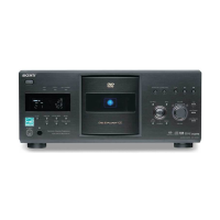
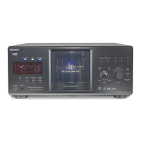
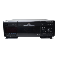
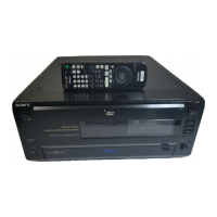
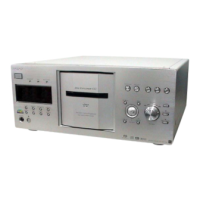
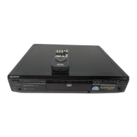
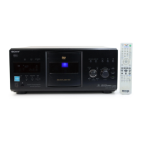
Identification and function of front panel, rear panel, and remote controls.

Disassembly Procedures

Mechanism Deck Block Removal

Steps for removing the CD/DVD mechanism deck block.

Motor Assemblies and Board Removal

Steps for removing the motor assemblies and loading motor board.

Optical Traverse Unit Removal

Steps for removing the optical traverse unit.

Test Mode Procedures

Entering Test Mode

Procedure to enter the test mode using the remote commander.

Drive Adjustment Procedures

Drive Auto Adjustment

Procedure for automatic adjustment of drive systems.

Disc Adjustment Steps

DVD Single Layer Disc Adjustment

Detailed sequence of steps for adjusting DVD single layer discs.

CD Disc Adjustment

Detailed sequence of steps for adjusting CD discs.

Dual Layer Disc Adjustments

DVD Dual Layer Disc (Parallel) Adjustment

Step-by-step adjustment for dual-layer DVD discs (parallel).

DVD Dual Layer Disc (Opposite) Adjustment

Specific note for the opposite dual-layer DVD adjustment.

Manual Drive Operation

Operation Commands

Commands for manual operation like search disc, play, pause, stop.

Servo Control

Control for servo functions like laser, focus, spindle, and tracking.

Memory Checks and Changer Operations

Changer Manual Move

Interface for manual changer operations.

Changer Mecha Check

Test Mode Functions

Video Level Adjustment

Procedure for adjusting video output levels.

Display Test Mode Execution

Instructions for executing display self-check modes.

Display and Key Checks

FL Tube Grid and Segment Check

Procedure for checking the FL tube grid and segment display.

SIRCS Reception Check

Procedure for checking SIRCS reception.

Key Check Procedure

Process for verifying the functionality of all keys.

Jog, LED, Keyboard and Display Results

Jog and LED Check

Procedure for checking Jog dial and LEDs.

Keyboard Check

Procedure for executing and checking keyboard input.

Mechanical Adjustment Procedures

Pop-Up Mechanism Adjustment

Detailed steps for adjusting the pop-up mechanism.

Table Sensor Adjustment

Procedure for adjusting the table sensor.

Electrical Adjustments

Optical Traverse Unit Check

Checking the optical traverse unit's performance and specifications.

Power Supply Check

Verifying power supply voltages using a digital voltmeter.

Video System Adjustment

Adjustments related to the video system, including output levels.

Video Output Level Checks

Progressive Video Output Level Adjustment

Procedure for adjusting progressive video output level.

S-Video Output S-Y Check

Checking the S-Video output signal quality.

S-Video Output S-C Check

Verifying the S-Video output color signal.

Component Video Output Y Check

Checking the Y component of the video output signal.

Component Video Output Checks

Component Video Output B-Y Check

Checking the B-Y component of the video output signal.

Component Video Output R-Y Check

Checking the R-Y component of the video output signal.

Disc Detect Sensor Adjustment

Disc Detect Sensor Adjustment Procedure

Adjustment for the disc detect sensor, following mechanical adjustments.

Diagrams Overview

Block Diagram - Servo Section

Block diagram illustrating the servo system's signal paths.

Printed Wiring Boards Information

RF Translation Board Details

RF Translation Board Layout

Printed wiring board layout for the RF translation board.

MB Board Layouts

MB Board (Side A) Layout

Printed wiring board layout for the MB board, side A.

MB Board Side B Layout

MB Section Schematic Diagrams

MB Section Schematic (1/7)

Schematic diagram for the MB board section 1.

MB Section Schematic Diagrams (Continued)

MB Section Schematic (2/7)

Schematic diagram for the MB board section 2.

MB Section Schematic (3/7)

Schematic diagram for the MB board section 3.

MB Section Schematic (4/7)

Schematic diagram for the MB board section 4.

MB Section Schematic (5/7)

Schematic diagram for the MB board section 5.

MB Section Schematic (6/7)

Schematic diagram for the MB board section 6.

MB Section Schematic (7/7)

Schematic diagram for the MB board section 7.

AV Board Schematic Diagrams

AV Board Schematic (1/5)

Schematic diagram for the AV board section 1.

AV Board Schematic Diagrams (Continued)

AV Board Schematic (2/5)

Schematic diagram for the AV board section 2.

AV Board Schematic (3/5)

Schematic diagram for the AV board section 3.

AV Board Schematic (4/5)

Schematic diagram for the AV board section 4.

AV Board Schematic (5/5)

Schematic diagram for the AV board section 5.

AV Board Printed Wiring Layouts

AV Board (Component Side) Layout

Printed wiring board layout for the AV board, component side.

AV Board (Conductor Side) Layout

Table Section Diagrams

Printed Wiring Boards - Table Section

Printed wiring board layouts for the table section.

Table Section Schematic

Table Section Schematic Diagram

Schematic diagram for the table section.

Driver Board Details

Printed Wiring Board - Driver Board

Printed wiring board layout for the driver board.

Driver Board Schematic

Driver Board Schematic Diagram

Schematic diagram for the driver board.

Panel-L Board Details

Printed Wiring Board - PANEL-L Board

Printed wiring board layout for the PANEL-L board.

Panel-L Board Schematic

Panel-L Board Schematic Diagram

Schematic diagram for the PANEL-L board.

Panel-R Board Details

Printed Wiring Boards - PANEL-R Section

Printed wiring board layouts for the PANEL-R section.

Panel-R and Key Board Schematics

IC Pin Function Descriptions

MB Board IC104 Pin Functions

Pin function details for IC104 on the MB board.

MB Board IC205 (CPU) Pin Functions

MB Board IC304 (System Controller) Pin Functions

MB Board IC401 (SACD Player) Pin Functions

AV Board IC401 (Converter) Pin Functions

Exploded Views

Overall Section Exploded View

Exploded view of the entire unit, showing main assemblies.

Front Panel Section Exploded View

Power Block Section Exploded View

Table Section Exploded View

Chassis Section Exploded View

Base (Door) Section Exploded View

CD/DVD Mechanism Deck Section-1 (Pop-Up Block)

CD/DVD Mechanism Deck Section-2 (Pulley Block)

CD/DVD Mechanism Deck Section-3 (Lever, Holder Block)

CD/DVD Mechanism Deck Section-4 (Gear, Motor Block)

Base Unit Section (DVBU65) Exploded View

Electrical Parts List

Related product manuals