Do you have a question about the Sony DVP-S715 and is the answer not in the manual?
Lists models in the DVP series.
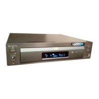
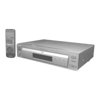
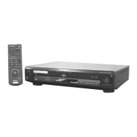
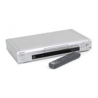
Shows physical dimensions and layout of player models.
Illustrates internal component layout for different player models.
Details the configuration and specifications of the disc drive mechanism.
High-level overview of the system's interconnected blocks.
Processes the RF signal from DVD discs.
Processes the RF signal from CD discs.
Handles RF signal processing and decryption.
Decodes digital copy protection for DVDs.
Decodes video and audio signals from DVD/VCD data.
Generates and overlays player menu and OSD signals.
Performs video noise reduction and encoding to NTSC/PAL.
Generates system clocks for audio decoding.
Decodes Dolby Digital (AC-3) bitstreams.
Processes stereo audio signals for line out.
Processes surround sound audio signals.
Block diagram specific to the AU-205 board.
Controls the overall system operations.
Manages communication with external devices and displays.
Overview of the servo system's fundamental circuits.
Servo control functions during DVD playback.
Servo control functions during CD/VCD playback.
Operations for disc loading and chucking.
Identifies disc types (CD, DVD-SL, DVD-DL).
Detailed block diagram of the servo system.
Details the ARP IC, including its block diagram and pin functions.
Details the AV Decoder IC, including its block diagram and pin assignment.
Details the DSP IC, including its pin assignment and functions.
Details the AC-3 Decoder IC, including its block diagram and pin functions.
Overall system block diagram covering RF, servo, audio, and power.
Detailed block diagram of the signal processing path.
Lists models in the DVP series.
Shows physical dimensions and layout of player models.
Illustrates internal component layout for different player models.
High-level overview of the system's interconnected blocks.
Processes the RF signal from DVD discs.
Processes the RF signal from CD discs.
Handles RF signal processing and decryption.
Decodes digital copy protection for DVDs.
Decodes video and audio signals from DVD/VCD data.
Generates and overlays player menu and OSD signals.
Performs video noise reduction and encoding to NTSC/PAL.
Generates system clocks for audio decoding.
Decodes Dolby Digital (AC-3) bitstreams.
Processes stereo audio signals for line out.
Processes surround sound audio signals.
Block diagram specific to the AU-205 board.
Controls the overall system operations.
Manages communication with external devices and displays.
Overview of the servo system's fundamental circuits.
Servo control functions during DVD playback.
Detailed focus servo operations for DVD playback.
Detailed focus servo operations for CD playback.
Controls the disc loading/chucking motor.
Detects the position of the disc tray.
Distinguishes between CD and DVD formats.
Differentiates between Single Layer and Dual Layer DVDs.
Details the process of differentiating disc types.
Details the ARP IC, including its block diagram and pin functions.
Details the AV Decoder IC, including its block diagram and pin assignment.
Details the DSP IC, including its pin assignment and functions.
Details the AC-3 Decoder IC, including its block diagram and pin functions.
Functional block diagram of the Large Gate Array IC.
Lists and describes the pins of the Large Gate Array IC.
Functional block diagram of the Middle Gate Array IC.
Lists and describes the pins of the Middle Gate Array IC.
Functional block diagram of the Small Gate Array IC.
Lists and describes the pins of the Small Gate Array IC.
Overall system block diagram covering RF, servo, audio, and power.
| Brand | Sony |
|---|---|
| Model | DVP-S715 |
| Category | DVD Player |
| Language | English |