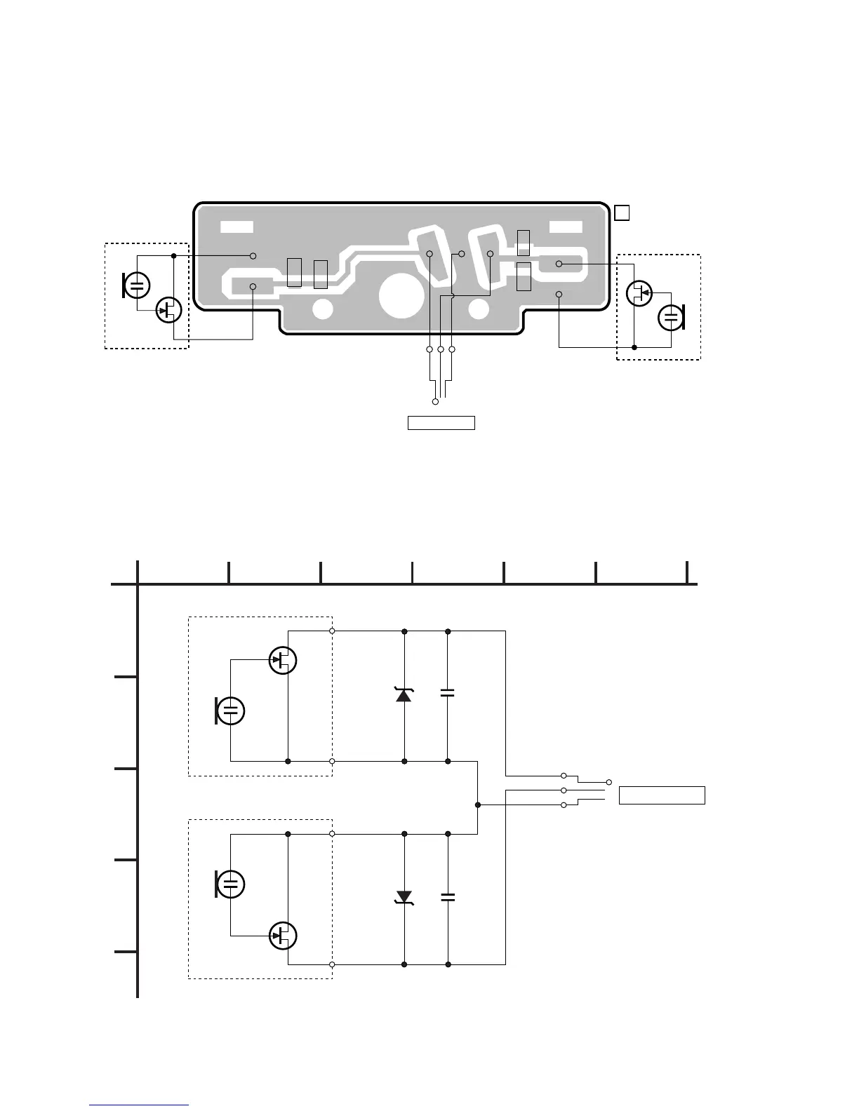
EasyManuals Logo

Sony ECM DS70P Service Manual

Sony ECM DS70P
6 pages
To Next Page IconTo Next Page
To Previous Page IconTo Previous Page
Page #2 background imageLoading...
Page #2 background image
– 2 –
SECTION 1
DIAGRAM
[PRINTED WIRING BOARD]
[SCHEMATIC DIAGRAM]
D1
C1
C2
GRN
GLD
RED
D2
P1
MIC OUTPUT
MIC 1
MIC 2
RED
RED
02
WHT
WHT
1-667-840-
11
[AMP BOARD]
C1
1000p
D1
UDZ-4.7
C2
1000p
D2
UDZ-4.7
S
02
S
MIC 2
MIC 1
P 1
MIC OUTPUT
L ch
R ch
1
A
B
C
D
23456
ECM-DS70P
Note on Schematic Diagram:
Note:
All capacitors are in µF unless otherwise noted. pF: µµF
50 WV or less are not indicated except for electrolytics
and tantalums.
Note on Printed Wiring Boards:
Note:
X : parts extracted from the component side.
b : Pattern on the side which is seen.

Other manuals for Sony ECM DS70P

Questions and Answers:

Question and Answer IconNeed help?

Do you have a question about the Sony ECM DS70P and is the answer not in the manual?

Sony ECM DS70P Specifications

General IconGeneral
Weight10 g
Connector(s)Gold-plated straight, mini
Dimensions (WxDxH)58 x 16 x 57 mm
Microphone frequency100 - 15000 Hz
Microphone sensitivity-38 dB
Microphone direction typeUnidirectional
Microphone operation modestereo
Power supply typeAC
Weight and Dimensions IconWeight and Dimensions
Depth16 mm
Width58 mm
Height57 mm

Related product manuals