4
ECM-S80
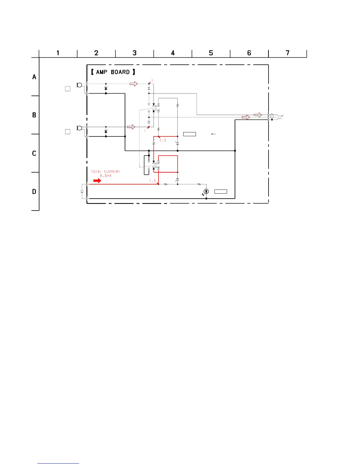
3-2. SCHEMATIC DIAGRAM
Note:
• All capacitors are in µF unless otherwise noted. pF: µµF 50 WV or
less are not indicated except for electrolytics and tantalums.
• All resistors are in Ω and
1
/
4
W or less unless otherwise specified.
• A : B+ Line.
• Voltages are dc with respect to ground under no-signal conditions.
• Voltages are taken with a VOM (Input impedance 10 MΩ).
Voltage variations may be noted due to normal production toler-
ances.
• Signal path.
F
MIC1
MIC2
D1
D2
C3
C4
R1
R2
R5
R6
D3
SW1
SW2
R7
C5
C6
P1
UDZSTE-17-4.7B
UDZSTE-17-4.7B
1
1
3.3k
3.3k
10k
470
SML-310LT
100
47
2.5V
47
2.5V
(OUTPUT)
ALKALINE MANGANESE BATTERY
LR44
1PC,1.5V
POWER
POWER
SW1,2
OFF
ON
(PLUG IN POWER)
R
L