Do you have a question about the Sony FD Trinitron KV-29LS60B and is the answer not in the manual?
| Screen Size | 29 inches |
|---|---|
| Display Type | CRT |
| Screen Type | Flat |
| Aspect Ratio | 4:3 |
| Audio Output | Stereo |
| Audio Output Power | 20W |
| Connectors | SCART, Composite, S-Video |
| Remote Control | Yes |
| Tuner | Analog |
Initial TV setup, language selection, auto channel tuning process.
Navigating TV menus, picture/sound adjustments, sleep timer, and system settings.
Instructions for accessing and using Teletext and Fastext features.
How to configure the remote to control external VCR/DVD devices.
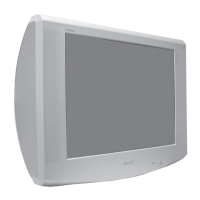
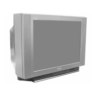
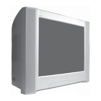
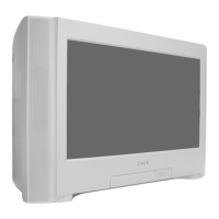
Technical details and features of the TV model.
Common problems and simple solutions for picture and sound issues.
Steps to remove the rear cover of the television for access.
Procedure for disconnecting speaker cables during disassembly.
Steps to safely remove and reinstall the main chassis assembly.
How to position the chassis for optimal access during servicing.
Detailed steps for removing the D and G circuit boards.
Procedure for removing the side control module.
Steps for removing the H2 circuit board.
Instructions for removing the M circuit board.
Information on using an extender board for M Board testing.
Detailed procedure for removing the picture tube, including safety warnings.
Guidance on removing and refitting bottom plates for chassis access.
Adjusting the picture beam for correct alignment on the screen.
Aligning the red, green, and blue electron beams for a clear image.
Adjusting the focus control for sharp picture clarity.
Adjusting G2 and white balance for optimal picture settings.
Performing electrical adjustments using the service remote commander.
Detailed instructions and functions for accessing and using Test Mode 2.
High-level overview of the TV's internal circuitry and signal flow.
Identifies the physical location of each circuit board within the TV.
Detailed electronic schematics and conductor patterns for the circuit boards.
Diagrams and identification of various semiconductor components used in the TV.
Internal block diagrams of key integrated circuits (ICs) used in the TV.
Exploded view showing major chassis components and their part numbers.
Exploded view detailing picture tube assembly components and part numbers.
Index of all electrical parts listed in the manual, with corresponding page numbers.