Do you have a question about the Sony FD Trinitron KV-32LS35E and is the answer not in the manual?
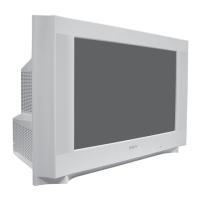
| Screen Size | 32 inches |
|---|---|
| Display Technology | CRT |
| Screen Type | Flat |
| Aspect Ratio | 4:3 |
| Tuner | Analog |
| Audio | Stereo |
| Remote Control | Yes |
| Inputs | Composite, S-Video |
| Sound Output | 10W x 2 |
Short circuit the anode of the picture tube and the anode cap to the metal chassis.
Use an isolation transformer during service work to avoid shock hazard.
Replace safety-critical components with Sony parts only.
Details on power requirements, consumption, dimensions, and weight.
Description of rear and side connection terminals for audio and video.
Procedure to enter the self-diagnostic mode and view error codes.
Table listing error codes and the TV's working time.
Initial setup process for channels, language, and picture rotation.
Customizing the order of broadcast channels.
Guide to operating the on-screen menu system using remote control buttons.
Adjusting contrast, brightness, color, sharpness, and hue.
Accessing language, auto tuning, and programme sorting settings.
How to access and use the teletext information service.
Configuring AV output signals and adjusting RGB picture position.
Correcting picture slant and using the Fastext service.
Connecting Hi-Fi equipment for amplified audio output.
Connecting VCRs, including those with Smartlink capability.
Selecting input sources and enjoying special sound effects.
Solutions for common picture and sound problems.
Detailed technical specifications including TV system, power, dimensions, and weight.
Steps for removing the rear cover and disconnecting speakers.
Procedure for safely removing and refitting the main chassis assembly.
Steps to remove the A Board Printed Wiring Board (PWB).
Procedure for removing the side control module for access.
Safe procedures for handling the anode cap and discharging high voltage.
Detailed instructions for removing the picture tube (CRT) from the set.
Procedure to adjust beam landing for optimal picture purity and color.
Steps to prepare the TV and equipment before performing adjustments.
Adjusting static convergence using H.STAT and V.STAT magnets.
Using BMC magnets to fine-tune convergence points.
Adjusting geometry using deflection yoke tilt and spacers.
Correcting screen corner convergence using permalloy magnets.
Adjusting the focus control on the flyback transformer for sharp picture.
Adjusting G2 control and white balance using service mode.
Entering service mode for electrical adjustments like Offset and Drive.
Adjusting sub-brightness and sub-contrast levels.
Adjusting sub-colour levels and tuner AGC voltage.
Adjusting deflection system parameters for optimal image geometry.
Description of functions accessible via Test Mode 1.
Description of functions accessible via Test Mode 2.
Block diagram showing power supply, deflection, and audio amplifier sections.
Diagrams showing the physical location of various circuit boards.
Reference information for schematic diagrams and printed wiring boards.
List and diagrams of common semiconductors used in the chassis.
Block diagrams illustrating the function of key ICs.
Exploded view of the chassis with part numbers and descriptions.
Exploded view of the picture tube assembly with part numbers.
Table of contents for the electrical parts lists by board and model.
List of parts for the F2 board.
List of parts for the F3 board.
Common components listed for the A board.
Specific parts list for A Board variant KV-28LS35.
Specific parts list for VM Board variant KV-32LS35.
List of parts for the D3 board.
Common parts list for the D2 board.
Specific parts list for VM Board variant KV-28LS35.
Complete parts list for the H2 board.
List of miscellaneous parts like switches, cords, and transformers.
Information on packaging materials and instruction manuals.
Details for the RM-932 remote commander.