 Loading...
Do you have a question about the Sony Handycam DCR-PC115 and is the answer not in the manual?
| Recording Media | MiniDV |
|---|---|
| Effective Pixels | 1.07 megapixels |
| Viewfinder | Color |
| Image Stabilization | Electronic |
| Microphone | Stereo |
| Image Sensor | 1/4 inch CCD |
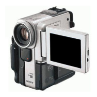
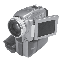
| LCD Screen | 2.5 inch |
| Interface | IEEE 1394 (FireWire), USB |
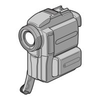
| Type | Digital Camcorder |