5-44
DCR-PC115/PC115E/PC120BT/PC120E
5-2. MECHANISM SECTION
ADJUSTMENT
On the mechanism section adjustment
For details of mechanism section adjustments, checks,
and replacement of mechanism parts, refer to the separate
volume “DV MECHANICAL ADJUSTMENT MANUAL
J Mechanism ”.
2-1. HOW TO ENTER RECORD MODE WITHOUT
CASSETTE
1) Connect the adjustment remote commander to the LANC jack.
2) Turn the HOLD switch of the adjustment remote commander
to the ON position.
3) Close the cassette compartment without the cassette.
4) Select page: 3, address: 01, set data: 0C, and press the PAUSE
button of the adjustment remote commander.
(The mechanism enters the record mode automatically.)
Note: The function buttons become inoperable.
5) To quit the record mode, select page: 3, address: 01, set data:
00, and press the PAUSE button of the adjustment remote
commander. (Whenever you want to quit the record mode, be
sure to quit following this procedure.)
2-2. HOW TO ENTER PLAYBACK MODE
WITHOUT CASSETTE
1) Connect the adjustment remote commander to the LANC jack.
2) Turn the HOLD switch of the adjustment remote commander
to the ON position.
3) Close the cassette compartment without the cassette.
4) Select page: 3, address: 01, set data: 0B, and press the PAUSE
button of the adjustment remote commander.
(The mechanism enters the playback mode automatically.)
Note: The function buttons become inoperable.
5) To quit the playback mode, select page: 3, address: 01, set data:
00, and press the PAUSE button of the adjustment remote
commander. (Whenever you want to quit the playback mode,
be sure to quit following this procedure.)
2-3. TAPE PATH ADJUSTMENT
1. Preparation for Adjustment
1) Clean the tape running side (tape guide, drum, capstan shaft,
pinch roller, etc.).
2) Connect the adjustment remote commander to the LANC jack.
3) Turn the HOLD switch of the adjustment remote commander
to the ON position.
4) Connect an oscilloscope to VC-270 board CN008 via the CPC-
6 flexible jig (J-6082-370-B) and CPC-6 terminal board jig (J-
6082-371-A).
Channel 1: VC-270 board, CN008 Pin w; (Note)
External trigger: VC-270 board, CN008 Pin qj
Note: Connect a 75 Ω resistor between pins w; of CN008 and ql
(GND).
75 Ω resistor (Parts code: 1-247-804-11)
5) Playback the alignment tape for tracking. (XH2-1)
6) Select page: 3, address: 33, and set data: 08.
7) Select page: 3, address: 26, and set data: 31.
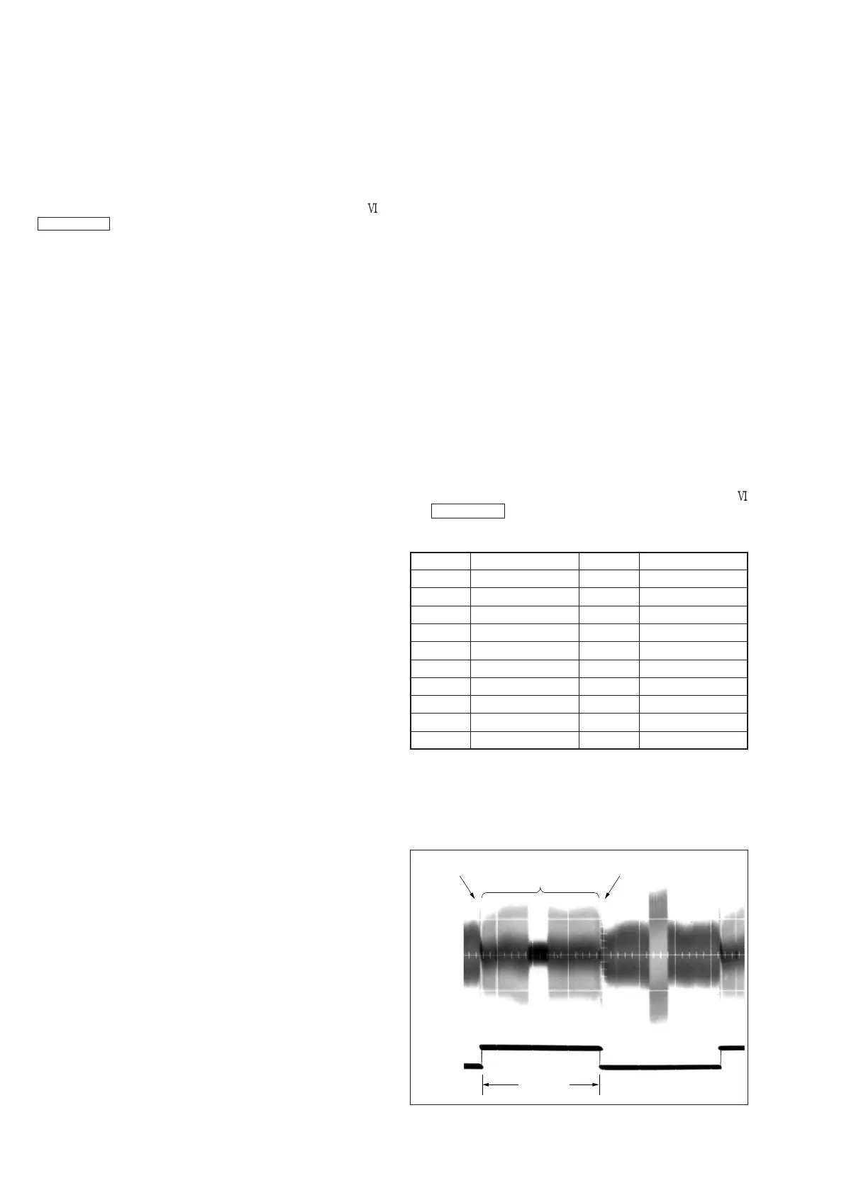
8) Check that the oscilloscope RF waveform is normal at the
entrance and exit.
If not normal, adjust according to the separate volume
“DV MECHANICAL ADJUSTMENT MANUAL
J Mechanism ” .
CN008 of VC-270 board
2. Procedure after operations
1) Connect the adjustment remote commander to the LANC jack
and set the HOLD switch to the ON position.
2) Select page: 3, address: 26, and set data: 00.
3) Select page: 3, address: 33, and set data: 00.
Fig. 5-2-1.
CH1
Entrance side Exit side
Check this section
(Normal waveform)
CH2
(Trigger)
3.3msec
Pin No.
1
3
5
7
9
11
13
15
17
19
Signal Name
LANC SIG
EVF LED DA
EVF VCO
PANEL VG
H START
PANEL COM
TCK
JIG TDO
SWP
GND
Pin No.
2
4
6
8
10
12
14
16
18
20
Signal Name
N.C.
EVF VG
GND
VCO
XHD/PSIG
TMS
JIG TDI
GND
RF IN/LANC JACK IN
RF MON
 Loading...