EasyManua.ls Logo

Sony HANDYCAM DCR-TRV130E User Manual

Sony HANDYCAM DCR-TRV130E
165 pages
To Next Page IconTo Next Page
Page #1 background imageLoading...
Page #1 background image
SERVICE MANUAL
US Model
Canadian Model
Korea Model
Brazilian Model
DCR-TRV130
AEP Model
UK Model
Australian Model
Chinese Model
DCR-TRV130E
E Model
Hong Kong Model
DCR-TRV130/TRV130E
SERVICE MANUAL
DIGITAL VIDEO CAMERA RECORDER
M2000 MECHANISM
SPECIFICATIONS
— Continued on next page —
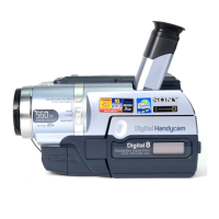
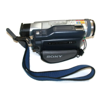
Photo : DCR-TRV130E
DCR-TRV130/TRV130E
RMT-814
NTSC model : DCR-TRV130
PAL model : DCR-TRV130E
For MECHANISM ADJUSTMENT, refer to the
“8mm Video MECHANICAL ADJUSTMENT
MANUAL
IX
M2000 MECHANISM ” (9-929-
861-11).
Level 2
On the VC-256 board
This service manual provides the information that is premised the
circuit board replacement service and not intended repair inside the
VC-256 board.
Therefore, schematic diagram, printed wiring board and electrical parts
list of the VC-256 board are not shown.
The following pages are not shown.
Printed wiring board ......................... Pages 4-61 to 4-64
Schematic diagram .......................... Pages 4-31 to 4-60
Electrical parts list ............................ Pages 6-15 to 6-22
Ver 1.2 2001. 11

Table of Contents

Question and Answer IconNeed help?

Do you have a question about the Sony HANDYCAM DCR-TRV130E and is the answer not in the manual?

Sony HANDYCAM DCR-TRV130E Specifications

General IconGeneral
BrandSony
ModelHANDYCAM DCR-TRV130E
CategoryCamcorder
LanguageEnglish

Summary

Safety-Related Component Warning!!

Safety Check-Out

Service Note

Power Supply During Repairs

Procedures to maintain power supply during repairs.

Self-Diagnosis Function

Adjustments

1. Before Starting Adjustment

Pre-adjustment checks and preparation guidelines.

1-1. Adjusting Items When Replacing Main Parts and Boards

Table indicating adjustments needed after component replacement.

1-3. Camera System Adjustments

Procedures for adjusting camera-related functions and parameters.

1-5. LCD System Adjustment

Procedures for adjusting the LCD display settings and parameters.

5-3. Servo and RF System Adjustment

Adjustments related to servo control and RF system parameters.

3-4. Video System Adjustments

Procedures for video signal processing and output adjustments.

3-6. Audio System Adjustments

Procedures for adjusting the camcorder's audio playback levels.

Service Mode

4-1. Adjustment Remote Commander

Instructions on how to use the remote commander for adjustments.

4-3. Service Mode

How to enter and use the service mode for diagnostics.

2-2. EMG Code (Emergency Code)

Table mapping error codes to specific failure types.

9. Record of Self-diagnosis Check

Interpreting self-diagnosis codes stored in memory.

Repair Parts List

Related product manuals