Do you have a question about the Sony HCD-DZ570 and is the answer not in the manual?
Notes on safe handling and electrostatic discharge prevention for optical pick-up blocks during repair.
Procedure for checking laser diode emission, emphasizing safe observation distance.
Instructions for locking and unlocking the disc tray for anti-theft purposes.
Warning against using specific cleaning discs or cleaners to prevent malfunction.
Caution regarding potential permanent damage to TV screens from static images.
Procedure for preparing the unit for customer return after repair.
Precautions for installing new optical pick-up units, including solder bridge handling.
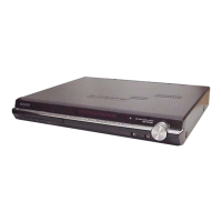
Identifies and locates parts and controls on the front and rear panels for specific models.
Explains the meaning of various indicators shown on the front panel display.
Lists all buttons on the remote control and their functions with page references.
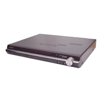
Identifies and locates parts and controls on the front and rear panels for DZ560 model.
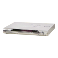
Identifies and locates parts and controls on the front and rear panels for DZ660 model.
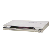
Identifies and locates parts and controls on the front and rear panels for DZ777 model.
Step-by-step guide for removing the outer case of the unit.
Instructions for removing the power supply board.
Procedure for disassembling the front panel components.
Guide for removing the back panel section.
Steps for removing the DVD drive mechanism assembly.
Procedure for removing the main control board.
Instructions for removing IO-SCART and IO-COMPONENT boards.
Steps for removing the disc tray assembly.
Guidance on replacing the belt in the disc mechanism.
Instructions for replacing the MS-203 board.
Steps for disassembling the base unit.
Procedure for replacing the optical pick-up unit.
Resets all system data and settings to initial conditions, used for customer returns.
Checks software version, FL display, and key inputs.
Enables/disables disc tray lock for anti-theft demonstration purposes.
Mode for returning the unit to the customer after repair.
Allows changing AM tuning step between 9 kHz and 10 kHz.
Moves optical pick-up and clears data; used for customer returns.
Performs diagnosis and adjustment using remote commander and TV monitor.
Procedure to check FM tuner sensitivity by inputting specific signals.
Diagrams showing the physical placement of various circuit boards within the unit.
High-level overview of the RF signal path and components.
Overview of the video signal processing path.
Diagram illustrating the audio signal flow and processing.
Overview of the amplifier circuitry and speaker outputs.
Diagram showing the power supply distribution and regulation.
Printed wiring boards and schematic diagrams for the main control board.
Diagrams for the IO-SCART interface board.
Diagrams for the IO-COMPONENT interface board.
Diagrams for the JACK and P-SW boards.
Diagrams for the FL display, MS-203, and SPEAKER boards.
Diagrams for the S-AIR-CON wireless communication board.
Diagrams for the power supply unit.
Exploded view showing the main chassis and major assemblies.
Exploded view of the front panel components.
Exploded view illustrating the chassis and related parts.
Exploded view of the DVD drive mechanism and its components.
List of parts for the FL board and associated holders.
Comprehensive list of all capacitors used in the system with specifications.
List of all connectors, including FFC/FPC and pin types.
List of all diodes used, including types and part numbers.
List of integrated circuits with part numbers and functions.
List of all coils and inductors used in the circuits.
Comprehensive list of transistors with part numbers and types.
List of all resistors with values, tolerance, and wattage.
List of fuses, terminal blocks, jacks, and switches.
| Channels | 5.1 |
|---|---|
| DVD Player | Yes |
| Bluetooth | No |
| USB Playback/Port | Yes |
| FM Tuner | Yes |
| HDMI Output | 1 |
| Tuner Bands | FM |
| CD Player | Yes |
| Type | Home Theatre System |
| Supported Formats | MP3, WMA |