Do you have a question about the Sony HCD-DZ777 and is the answer not in the manual?
Details rated and RMS output power for stereo and surround modes.
Lists inputs, outputs, audio decoders, USB, S-AIR, and other system features.
Covers tuner ranges, video outputs, power requirements, and consumption.
Lists model names, their corresponding regions, and part numbers.
Guidelines for using unleaded solder and handling chip components.
Precautions for flexible board repair and warnings about screen damage.
Details supported disc types (DVD, CD, Data) and their formats.
Describes characteristics and icons for playable disc types.
Lists examples of discs the system cannot play and notes on CD/DVD recording.
Information on copyright protection technologies and DualDisc playback limitations.
Explains multi-session CD playback and region code restrictions for DVDs.
Covers software-dependent playback features and product copyright information.
Explains the self-diagnosis function and how to interpret error codes.
Notes on displaying the version number for service purposes.
Introduces the exploded views section and lists its sub-sections.
Introduces the electrical parts list and its purpose.
Precautions for handling optical pick-up blocks and laser diodes.
Instructions for the disc tray lock function and unit transport preparation.
Warnings about screen damage and general handling during servicing.
Guidance for installing new optical pick-up units and related precautions.
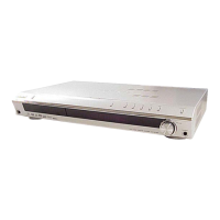
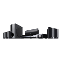
Identifies and describes controls and indicators on the front panel.
Identifies and describes the rear panel connection jacks.
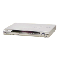
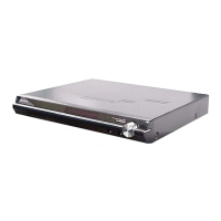
Identifies parts and controls on the DZ560 front and rear panels.
Identifies connection jacks on the DZ560 front and rear panels.
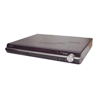
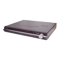
Identifies parts and controls on the DZ660 front and rear panels.
Identifies connection jacks on the DZ660 front and rear panels.
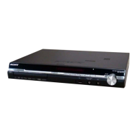
Identifies parts and controls on the DZ777 front and rear panels.
Identifies connection jacks on the DZ777 front and rear panels.
Outlines the sequence for disassembling the unit and lists components with page references.
Procedures for performing cold reset and various panel tests.
Instructions for disc tray lock, DVD ship mode, AM step change, and product out.
Explains the IOP measurement process and how to enter test mode.
Step-by-step guide for performing IOP measurement.
How to check and interpret emergency history error codes.
Procedures for clearing laser hours, emergency history, and setup data.
How to return to the diagnosis menu and check version information.
Procedures for acoustic field calibration test and demo playout mode.
Steps to perform a test on the Digital Media Port (DMPORT).
Procedure for checking and adjusting FM tuner sensitivity.
Common notes and abbreviations used in diagrams and schematics.
Visual guide to the location of various circuit boards within the unit.
Illustrates the signal flow for the RF section of the device.
Block diagrams for power amplifier ICs like CXD9883M.
Block diagrams for system control ICs like CXD9917R.
Block diagrams for LC89056W-E and system control ICs.
Block diagrams for MM1758AFBE video driver ICs on IO boards.
Block diagrams for MC14052BDR2 multiplexer ICs used for input selection.
Block diagram for the STR-F6138/F6168 power supply IC.
Block diagrams for SI-3010KM-TL voltage regulator ICs.
Details pin assignments and descriptions for the CXD9917R IC on the Main board.
Continues pin assignments and descriptions for IC1101.
Continues pin assignments and descriptions for IC1101.
Final pin assignments and descriptions for IC1101 on the Main board.
Details pin assignments and descriptions for the IC501 system control IC.
Continues pin assignments and descriptions for IC501.
Lists parts for the overall exploded view with part numbers and descriptions.
Important notes on parts, standardization, and abbreviations used.
Lists parts and their details for the chassis exploded view.
Lists components like capacitors, connectors, diodes, ICs, coils, transistors, resistors, transformers.
Lists fuses, thermistors, varistors, boards, switches, and miscellaneous items.
| Tuner | FM/AM |
|---|---|
| Remote Control | Yes |
| Disc Playback | CD |
| Audio Formats Supported | MP3 |
| Total Power Output | 100W |