HCD-GTR333/GTR555/GTR777/GTR888
5
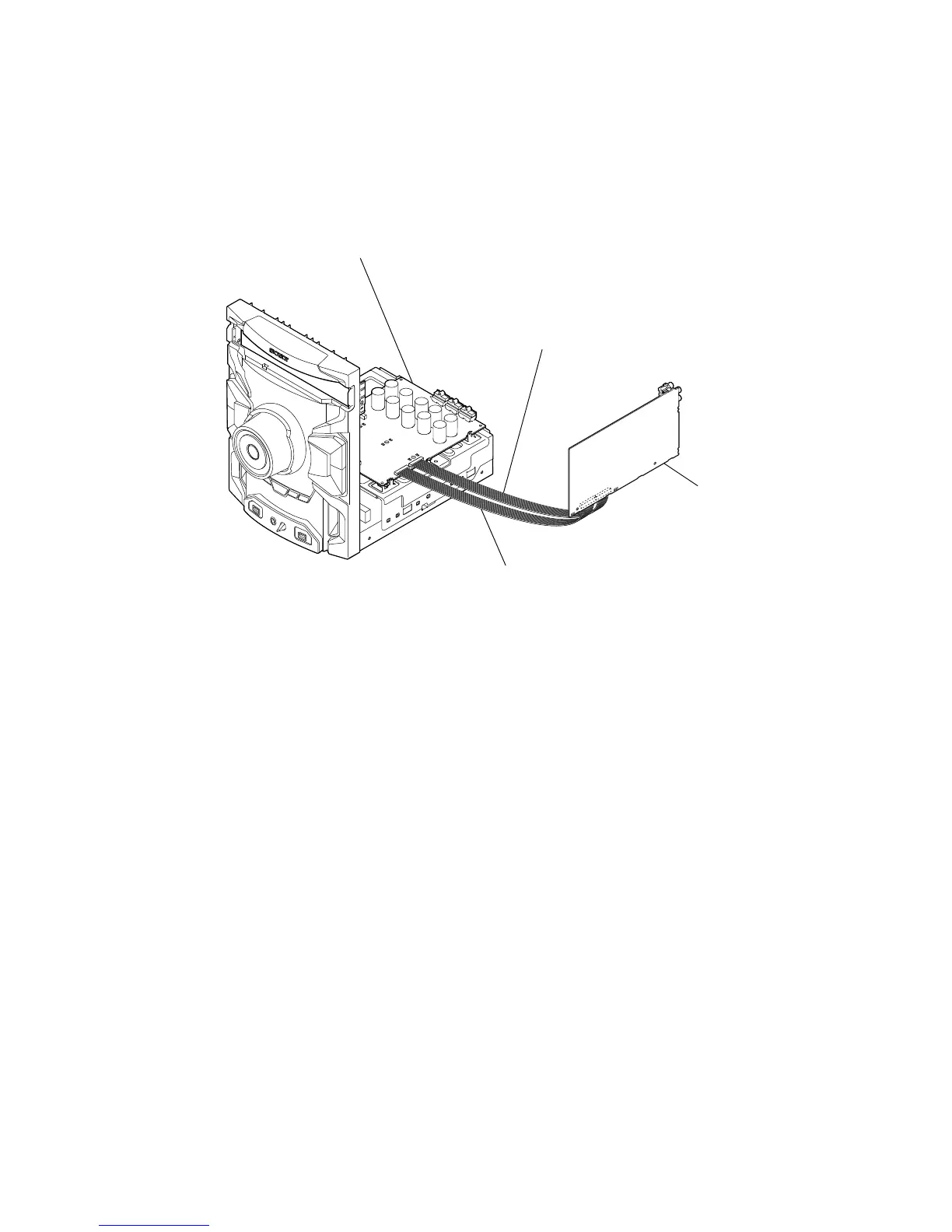
MICOM (IC500) ON MAIN BOARD SERVICE POSITION
• In checking the MICOM (IC500) on the MAIN board, prepare two extension jigs (1-843-138-11: 14 cores, 150 mm (common)/
1-843-140-11: 10 cores, 150 mm (for 2CH DAMP board)/ 1-843-139-11: 12 cores, 150 mm (for 3CH DAMP board)/ 1-843-138-11:
14 cores, 150 mm (for 4CH DAMP board).
HCD-GTR333
Connect jig (extension cable 1-843-140-11) to the
2CH DAMP BOARD (CN4001) (10 PIN) and
MAIN board (CN504) (10 PIN)
HCD-GTR555/HCD-GTR777
Connect jig (extension cable 1-843-139-11) to the
3CH DAMP BOARD (CN4001) (12 PIN) and
MAIN board (CN503) (12 PIN)
HCD-GTR888
Connect jig (extension cable 1-843-138-11) to the
4CH DAMP BOARD (CN4001) (14 PIN) and
MAIN board (CN502) (14 PIN)
Connect jig (extension cable 1-843-138-11) to the
2CH DAMP board (HCD-GTR333)
3CH DAMP board (HCD-GTR555/HCD-GTR777)
4CH DAMP board (HCD-GTR888)
(CN4000) (14 PIN) and MAIN board (CN501) (14 PIN)
2CH DAMP board (HCD-GTR333)
3CH DAMP board (HCD-GTR555/HCD-GTR777)
4CH DAMP board (HCD-GTR888)
MAIN board
Ver. 1.1
 Loading...