SERVICE MANUAL
COMPACT DISC DECK RECEIVER
US Model
Canadian Model
HCD-GX355/GX555
AEP Model
UK Model
Australian Model
HCD-RG270/RG475
E Model
HCD-RG270/RG475/RG575
HCD-GX355/GX555/
RG270/RG475/RG575
Ver. 1.2 2005.05
SPECIFICATIONS
9-879-533-03
2005E05-1
© 2005.05
Sony Corporation
Personal Audio Group
Published by Sony Engineering Corporation
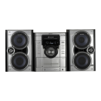
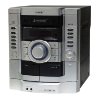
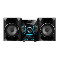
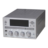
Photo: HCD-RG575
HCD-GX355 is the amplifier, CD player, tape deck
and tuner section in MHC-GX355.
HCD-GX555 is the amplifier, CD player, tape deck
and tuner section in MHC-GX555.
HCD-RG270 is the amplifier, CD player, tape deck
and tuner section in MHC-RG270.
HCD-RG475 is the amplifier, CD player, tape deck
and tuner section in MHC-RG475S.
HCD-RG575 is the amplifier, CD player, tape deck
and tuner section in MHC-RG575S.
Amplifier section
AUDIO POWER SPECIFICATIONS
(HCD-GX555/GX355 USA model only)
HCD-GX555
POWER OUTPUT AND TOTAL HARMONIC
DISTORTION:
With 6 ohm loads, both channels driven, from
120 – 10,000 Hz: rated 145 watts per channel
minimum RMS power, with no more than 10%
total harmonic distortion from 250 milliwatts to
rated output.
HCD-GX355
POWER OUTPUT AND TOTAL HARMONIC
DISTORTION:
With 6 ohm loads, both channels driven, from
120 – 10,000 Hz: rated 150 watts per channel
minimum RMS power, with no more than 10%
total harmonic distortion from 250 milliwatts to
rated output.
North American model:
HCD-GX555
Front speaker
Continuous RMS power output (reference):
145 + 145 watts (6 ohms at
1 kHz, 10% THD)
Total harmonic distortion less than 0.07% (6 ohms at
1kHz, 80 W)
Sub woofer
Continuous RMS power output (reference):
170 watts (6 ohms at
80 Hz, 10% THD)
Total harmonic distortion less than 0.07% (6 ohms at
80 Hz, 90 W)
HCD-GX355
Continuous RMS power output (reference):
150 + 150 watts (6 ohms at
1 kHz, 10% THD)
Total harmonic distortion less than 0.07% (6 ohms at
1kHz, 80 W)
European and Russian models:
HCD-RG475
Front speaker
DIN power output (rated): 110 + 110 watts (6 ohms at
1kHz, DIN)
Continuous RMS power output (reference):
140 + 140 watts (6 ohms at
1kHz, 10% THD)
Music power output (reference):
280 + 280 watts (6 ohms at
1kHz, 10% THD)
Sub woofer
DIN power output (rated): 130 watts (6 ohms at
80 Hz, DIN)
Continuous RMS power output (reference):
160 watts (6 ohms at
80 Hz, 10% THD)
Music power output (reference):
320 watts (6 ohms at
80 Hz, 10% THD)
HCD-RG270
DIN power output (rated): 80 + 80 watts (6 ohms at
1kHz, DIN)
Continuous RMS power output (reference):
100 + 100 watts (6 ohms at
1kHz, 10% THD)
Music power output (reference):
200 + 200 watts (6 ohms at
1kHz,
10% THD)
– Continued on next page –
Model Name Using Similar Mechanism NEW
CD CD Mechanism Type
CDM74KFS-F1BD81C (Except Mexican model)/
CDM74KFS-F1BD84 (Mexican model)
Section
Base Unit Name BU-F1BD81C (Except Mexican model)/BU-F1BD84 (Mexican model)
Optical Pick-up Block Name KSM-215DCP
TAPE Model Name Using Similar Mechanism NEW
Section Tape Transport Mechanism Type CWM43FF13