SERVICE MANUAL
COMPACT DISC DECK RECEIVER
US Model
Canadian Model
Ver. 1.3 2008.09
SPECIFICATIONS
9-887-123-04
2008I05-1
© 2008.09
Sony Corporation
Audio&Video Business Group
Published by Sony Techno Create Corporation
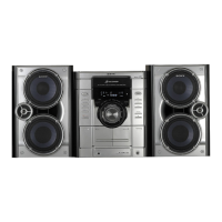
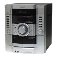
Photo: HCD-GX470
• HCD-GX470 is the amplifier, CD player, tape
deck and tuner section in MHC-GX470.
• HCD-GX570 is the amplifier, CD player, tape
deck and tuner section in MHC-GX570.
Main unit
AUDIO POWER SPECIFICATIONS
POWER OUTPUT AND TOTAL HARMONIC
DISTORTION: (The United States model only)
With 6 ohm loads, both channels driven, from
120 − 10,000 Hz; rated 125 watts per channel
minimum RMS power, with no more than 10%
total harmonic distortion from 250 milliwatts to
rated output.
Amplifier section
GX470
GX570
Front speaker
Continuous RMS power output
(reference): 125 + 125 watts (6 ohms at
1 kHz, 10% THD)
Total harmonic distortion: less than 0.07%
(6 ohms at 1 kHz, 80 W)
Subwoofer
Continuous RMS power output
(reference): 150 watts (6 ohms at 80 Hz,
10% THD)
Total harmonic distortion: less than 0.07%
(6 ohms at 80 Hz, 90 W)
Front speaker:
Continuous RMS power output (reference):
145 + 145 W (6 ohms at 1 kHz, 10% THD)
Total harmonic distortion: less than 0.07%
(6 ohms at 1 kHz, 80 W)
Subwoofer:
Continuous RMS power output (reference):
170 W (6 ohms at 80 Hz, 10% THD)
Total harmonic distortion: less than 0.07%
(6 ohms at 80 Hz, 90 W)
Inputs
AUDIO IN (stereo mini jack): voltage 250 mV,
impedance 47 kilohms
Outputs
PHONES (stereo mini jack):
accepts headphones of 8 ohms or more
SPEAKER: accepts impedance of 6 to 16 ohms
SUBWOOFER OUT:
accepts impedance of 6 to 16 ohms
Inputs:
AUDIO IN (stereo mini jack): voltage
250 mV, impedance 47 kilohms
Outputs:
PHONES (stereo mini jack): accepts
headphones of 8 ohms or more
SPEAKER: accepts impedance of 6 to
16 ohms
SUBWOOFER OUT: accepts
impedance of 6 to 16 ohms
CD player section
System: Compact disc and digital audio system
Laser Diode Properties
Emission duration: continuous
Laser Output*: Less than 44.6µW
*This output is the value measurement at a
distance of 200mm from the objective lens
surface on the Optical Pick-up Block with 7mm
aperture.
Frequency response: 20 Hz − 20 kHz
Signal-to-noise ratio: More than 90 dB
Dynamic range: More than 90 dB
Tape deck section
Recording system: 4-track 2-channel, stereo
Frequency response: 50 − 13,000 Hz (±3 dB),
using Sony TYPE I cassettes
– Continued on next page –
Model Name Using Similar Mechanism HCD-GX555
CD CD Mechanism Type CDM74KF-K6BD83S
Section Base Unit Name BU-K6BD83S-WOD
Optical Pick-up Block Name KSM-213DCP
TAPE Model Name Using Similar Mechanism NEW
Section Tape Transport Mechanism Type CWN42FF609
HCD-GX470/GX570