21
HCD-GX470/GX570
3. Mode: Playback
set
test tape
P-4-A063
(6.3 kHz, –10 dB)
oscilloscope
V
H
waveform of oscilloscope
in phase 45
°
90
°
135
°
180
°
good
wrong
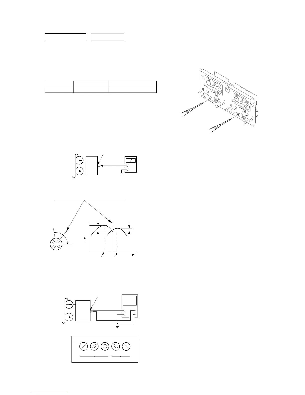
MIC. AUX. HP board
PHONES jack
(J701)
2. Turn the adjustment screw and check output peaks. If the peaks
do not match for L-CH and R-CH, turn the adjustment screw
so that outputs match within 1dB of peak.
Screw
position
L-CH
peak
within
1dB
Output
level
L-CH
peak
R-CH
peak
within
1dB
Screw
position
R-CH
peak
SECTION 6
ELECTRICAL ADJUSTMENTS
0 dB=0.775 VDECK SECTION
set
MIC. AUX. HP board
PHONES jack
(J701)
+
–
level mete
test tape
P-4-A063
(6.3 kHz, –10 dB)
1. Demagnetize the record/playback head with a head
demagnetizer.
2. Do not use a magnetized screwdriver for the adjustments.
3. After the adjustments, apply suitable locking compound to the
parts adjust.
TEST TAPE
RECORD/PLAYBACK HEAD AZIMUTH ADJUSTMENT
Note 1:Remove the mecha deck before this adjustment.
(Refer to Section 3. DISASSEMBLY (See page 9))
Note 2:Perform this adjustment for both decks.
Procedure:
1. Mode: Playback
Tape Signal Used for
P-4-A063 6.3 kHz, -10 dB Azimuth Adjustment
4. After the adjustments, apply suitable locking compound to
the pats adjusted.
Adjustment Location: Playback Head (DECK-A)
Record/Playback/Erase Head (DECK-A)
 Loading...