Do you have a question about the Sony HCD-GZR7D and is the answer not in the manual?
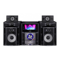
Details power output ratings for MHC-GZR9D model.
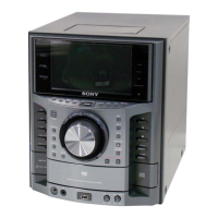
Details power output ratings for MHC-GZR8D model.
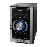
Details power output ratings for MHC-GZR7D model.
Lists input signal types, voltage, and impedance levels.
Procedure for electrostatic prevention when handling the OP section.
Visual guide for the correct service position of the DVD mechanism deck.
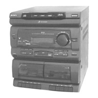
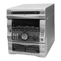
Identifies main controls and parts of the unit and remote.
Steps for removing the main case and the loading panel.
Procedures for disassembling the front panel and DVD block.
Resets system data to factory defaults.
Checks audio levels and VACS status.
Verifies VACS levels and amplifier adjustments.
Guidelines for cleaning, demagnetizing, and tool usage.
Specifies torque values for mechanical parts like motor tension.
Procedure to execute IOP measurement after optical pick-up replacement.
Procedure to check RFMON signal waveform clarity.
Procedure for checking FM tuning using a signal generator.
Diagram showing the placement of various circuit boards.
Illustrates signal flow for RF and servo systems.
Shows signal paths for video processing, input, and output.
Comprehensive diagram of main control and signal processing units.
Illustrates audio signal processing, amplification, and speaker output.
Shows signal flow for display control and power management.
Layout of the driver board's printed wiring.
Detailed circuit schematic for the DMB18 board.
Exploded diagram of the entire unit for parts identification.
Exploded diagrams showing components of the front panel sections.
Exploded view detailing components mounted on the back panel.
Exploded diagrams illustrating DVD mechanism deck assembly parts.
List of electrical components for the AMP FR & SW board.
Comprehensive list of components for the DMB18 circuit board.
Detailed listing of transistors with part numbers and descriptions.
Catalog of capacitors including part numbers, values, and ratings.
Enumeration of diodes with their part numbers and board locations.
Comprehensive list of integrated circuits and their corresponding part numbers.
| Type | Mini Hi-Fi System |
|---|---|
| Number of Discs | 1 |
| Audio Output Mode | Stereo |
| Cassette Deck | Yes |
| CD Player | Yes |
| Speaker Output | 2 speakers |
| Functions | CD Player, Cassette Deck, Radio |
| Audio Output Power | 100W |
| Tuner Bands | AM/FM |
| Speaker Power Output | 50W |