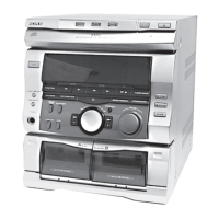
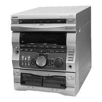
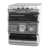
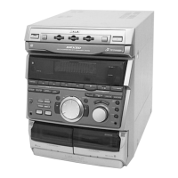
Do you have a question about the Sony HCD-GR8 and is the answer not in the manual?
Details specifications for the CD playback system.
Details specifications for the tape playback system.
Precautions for handling the optical pick-up block or base unit.
Guidelines for safely checking laser diode emission.
Notes on replacing chip components, especially tantalum capacitors.
Guide to setting up and connecting the system for initial use.
Step-by-step instructions for connecting speakers and antennas.
Procedure for setting the system's clock and timer functions.
Guide to saving radio stations into memory for quick access.
Instructions for connecting external audio and video devices.
Core operational functions of the system.
Additional functions and system features.
Instructions for using the karaoke function, including voice reduction.
Setting the timer for the system to turn off after a specified duration.
Setting the Wake-up Timer to start playback at a specific time.
Recording radio programs automatically using the timer function.
Supplementary information and precautions for system use.
Important safety and operational precautions for the system.
How to play CDs, including normal play and disc exchange.
Instructions for recording CDs onto tape using CD Synchro.
How to tune and listen to preset radio stations.
Procedure for recording radio broadcasts onto tape.
How to play audio tapes in deck A or B.
Instructions for dubbing tapes, including high-speed dubbing.
Features and operations related to the CD playback functionality.
How to create custom playback sequences for CDs.
Features for continuous playback or mixing applause between tracks.
Manual operations for recording and playing tapes.
Recording CDs onto tape with a specified track sequence.
Function to automatically select tape length for recording.
Special audio effects for creative sound manipulation.
Creating rhythms automatically using the beat function.
Adjusting sound settings like bass reinforcement and headphone output.
Selecting different speaker configurations for various listening situations.
Utilizing RDS features for station information and program type search.
Instructions for removing the outer case of the unit.
Steps for disassembling the front panel assembly.
Disassembly steps for the CD mechanism deck.
Disassembly steps for the tape mechanism deck.
Disassembly of the base unit assembly.
Steps for accessing and removing the main circuit board.
Disassembly steps for the disc tray mechanism.
Steps for disassembling the BD (Blu-ray Disc) board.
Disassembly of the optical pick-up and sled motor assembly.
Disassembly procedures for the audio circuit board.
Steps for removing the capstan motor assembly.
Resets all data, including preset data, to initial conditions.
Moves the pickup to a position durable to vibration for shipping.
Resets the preset data while keeping it stored in memory.
Allows free operation of the CD sled motor, useful for cleaning.
Adjusts the AM tuner step between 9kHz and 10kHz.
Activates all LEDs and the fluorescent tube for key check mode.
Operating method and sequence for CD aging mode.
Operating method and sequence for tape deck aging mode.
Important precautions before performing mechanical adjustments.
Specifications and methods for torque measurements.
Specifications and methods for tape tension measurements.
Electrical adjustments specific to the tape deck section.
Adjusting the azimuth for optimal record/playback head alignment.
Adjusting tape playback speed for accurate recording and playback.
Adjusting playback signal levels for optimal output.
Adjustments for the AM reception section.
Adjusting the input signal level for AM tuning.
Adjustments for the FM reception section.
Adjusting the input signal level for FM tuning.
Performing an S-curve check on the CD pickup for signal symmetry.
Checking the RF signal level for optimal CD playback.
Illustration showing the location of various circuit boards within the unit.
Printed wiring diagram for the tuner section.
Schematic diagram for the tuner section.
Printed wiring diagram for the CD section.
Schematic diagram for the CD section.
Printed wiring diagrams for CD motor boards.
Schematic diagram for the CD motor section.
Printed wiring diagrams for the tape deck section.
Schematic diagram for the tape deck section.
Schematic diagram for the main and power supply sections.
Printed wiring diagrams for main and power boards.
Schematic diagram for the panel section, including display and controls.
Printed wiring diagrams for the panel section.
Printed wiring diagram for the power amplifier section.
Schematic diagram for the power amplifier section.
Block diagram for IC21, LC72130, on the TCB board.
Block diagram for IC41, LA1835, on the TCB board.
Block diagram for IC1701, IR3R42, on the TCB board.
Block diagram for IC1702, MC14053BCP, on the TCB board.
Block diagram for IC101, CXA1992AR, on the BD board.
Block diagram for IC102, BA5941FP-E2, on the BD board.
Block diagram for IC103, CXD2519Q, on the BD board.
Block diagram for IC281, μPC1237HA, on the main board.
Block diagram for IC602, μPC1330HA, on the audio board.
Block diagram for IC701, M54641L, on the motor turn board.
Block diagram for IC801, BA6286N, on the motor slide board.
Block diagram for IC901, LA5617, on the main board.
Block diagram for IC1502, LB1641, on the main board.
Block diagram for IC401, MSM6653A-485RS, on the DJ board.
Pin function description for the main control IC on the main board.
Pin function description for IC601 on the panel board.
Exploded view of the case and MD assembly section.
Exploded view of the front panel assembly.
Exploded view of the main chassis and power components.
Exploded view of the first part of the CD mechanism deck.
Exploded view of the second part of the CD mechanism deck.
Exploded view of the base unit assembly with optical pick-up.
Exploded view of the first part of the tape mechanism deck.
Exploded view of the second part of the tape mechanism deck.
Parts list for audio components, including capacitors, connectors, ICs, and resistors.
Parts list for components on the BD board.
Parts list for components on the CD SW board.
Parts list for various connectors used in the system.
Parts list for components on the DJ board.
Parts list for components on the HP/MIC board.
Parts list for components on the LEAF SWITCH board.
Parts list for components on the MAIN board.
Parts list for panel components.
Parts list for components on the POWER AMP board.
Parts list for components on the TCB board.
Parts list for components on the TRANS board.
List of hardware components used in the system.
List of included accessories with the system.
How to print specific sections of large documents using page range.
| CD Player | Yes |
|---|---|
| Tuner | FM/AM |
| USB Port | No |
| MP3 Playback | Yes |
| Remote Control | Yes |
| Bluetooth | No |
| Type | Mini Hi-Fi System |
| Functions | CD |
| Tuner Bands | FM, AM |