EasyManua.ls Logo

Sony HCD-GR10AV User Manual

Sony HCD-GR10AV
88 pages
To Next Page IconTo Next Page
Page #1 background imageLoading...
Page #1 background image
— 1 —
SERVICE MANUAL
COMPACT DISC DECK RECEIVER
— Continued on next page —
Model Name Using Similar Mechanism HCD-H991AV
CD Mechanism Type CDM38L-5BD29AL
Base Unit Type BU-5BD29AL
Optical Pick-up Type KSS-213D/Q-NP
Model Name Using Similar Mechanism HCD-H991AV
Tape Transport Mechanism Type TCM-220WR2
CD
SECTION
TAPE
DECK
SECTION
SPECIFICATIONS
US Model
HCD-D90AV/RX100AV
Canadian Model
AEP Model
UK Model
HCD-RX100AV
E Model
Australian Model
Tourist Model
HCD-GR10AV
Photo : HCD-RX100AV : US model
HCD-D90AV/GR10AV/RX100AV is the
tuner, deck, CD and amplifier section in
MHC-D90AV/GR10AV/RX100AV.
HCD-D90AV/GR10AV/
RX100AV
MICROFILM

Table of Contents

Question and Answer IconNeed help?

Do you have a question about the Sony HCD-GR10AV and is the answer not in the manual?

Sony HCD-GR10AV Specifications

General IconGeneral
CD PlayerYes
Cassette DeckYes
TunerAM/FM
Remote ControlYes
TypeMini Hi-Fi System
Power Output100 W
Speakers2
Audio Inputs2 x Audio In

Summary

Servicing Note

Open Disc Tray When Power Off

Procedure to open disc tray when unit is powered off.

General

Parts and Controls Overview

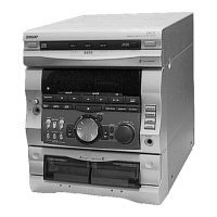
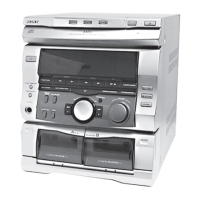
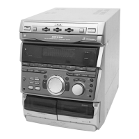
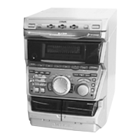
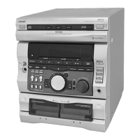
Identifies and describes front panel controls and parts.

Disassembly

Disassemble Loading Panel

Steps for disassembling the loading panel mechanism.

Remove Front Panel

Procedure for removing the front panel assembly.

Disassemble TC Mechanism Deck

Disassembly of the TC mechanism deck and deco board.

Remove Disc Tray

Procedure for removing the disc tray assembly.

Service Mode

Service Mode: Cold Reset

Resets all data to initial conditions, clearing preset data.

Service Mode: CD Delivery Mode

Moves pickup to a position durable to vibration for transport.

Service Mode: Aging Test

Used for operation check of CD and tape deck sections.

Mechanical Adjustments

Mechanical Adjustments: Torque Measurement

Details torque measurements for tape deck mechanisms.

Electrical Adjustments

Electrical Adjustments: Azimuth

Procedure for adjusting record/playback head azimuth.

Electrical Adjustments: Tape Speed

Method for adjusting tape speed in Deck A.

Electrical Adjustments: Playback Level

Procedure to adjust playback signal levels for both decks.

Diagrams

Diagrams: Circuit Board Locations

Illustrates location of various circuit boards within the unit.

Diagrams: Tuner Block Diagram (AEP/UK/German)

Block diagram for tuner section of specific models.

Diagrams: CD Section Wiring Board

Printed wiring board layout for the CD section.

Diagrams: Main Section Schematic

Schematic diagram for the main section of the unit.

Diagrams: IC Block Diagrams

Block diagrams illustrating internal functions of key ICs.

Exploded Views

Exploded Views: Case Section

Exploded view of unit's case and front panel components.

Exploded Views: Main Board

Exploded view detailing main board assembly and related parts.

Exploded Views: TC Mechanism Section 1

Exploded view of the TC mechanism section 1.

Electrical Parts List

Parts List: Audio Section

List of electrical parts for audio section, including connectors and components.

Parts List: BD SW Section

Electrical parts list for BD SW section, including resistors and transistors.

Parts List: TCB Section

Electrical parts list for TCB section, including capacitors, diodes, and ICs.

Related product manuals