Do you have a question about the Sony HCD-GR8000 and is the answer not in the manual?
RMS power output ratings for different regions and conditions.
Voltage, frequency, and power consumption specifications.
Guidelines for safely handling the optical pick-up block.
Procedure for safely checking laser diode emissions.
Specific advice for replacing chip components.
Instructions for repairing flexible circuit boards.
Visual guide to the location of various circuit boards.
Detailed schematic for the main section (Part 1/2).
Detailed schematic for the main and power sections.
Printed wiring board layout for main and power sections.
Schematics and printed wiring for the power amplifier section.
Exploded view of the unit's case and MD assembly.
Exploded view of the front panel components.
Exploded view of the chassis and related components.
List of capacitors and resistors used in the unit.
List of diodes, integrated circuits, and transistors.
List of connectors and switches.
Continuation of resistor and transistor part listings.
List of variable resistors, relays, and terminals.
Specific parts list for the power board.
List of transformers, fuses, and miscellaneous parts.
List of screws, wires, and other hardware.
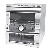
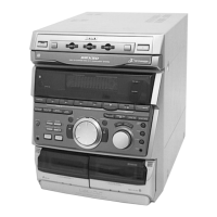
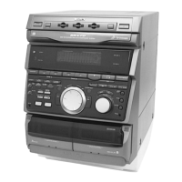
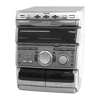
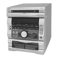
The HCD-GR8000 is a comprehensive compact disc deck receiver, serving as the central audio component within the MHC-GR8000 system. This unit integrates a tuner, dual cassette decks, a compact disc player, and an amplifier, offering a versatile range of audio playback and recording capabilities. Designed for the E Model, its mechanical and electrical specifications largely align with the HCD-GR7 E model, with this manual focusing on the differentiating aspects.
At its core, the HCD-GR8000 functions as a multi-source audio system, allowing users to enjoy music from various formats. The integrated compact disc player supports standard audio CDs, providing high-fidelity digital playback. The dual cassette deck system offers both playback and recording functionalities for analog audio tapes. This dual-deck configuration is particularly useful for tape-to-tape dubbing, allowing users to create copies of their cassettes. The tuner section enables reception of radio broadcasts, likely covering FM and AM bands, providing access to a wide array of radio programming.
The amplifier section is responsible for boosting audio signals from the various sources to drive connected loudspeakers. This integrated design ensures optimal compatibility and performance between the source components and the amplification stage. The system is designed to deliver a robust audio experience, suitable for home entertainment.
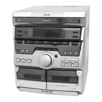
The HCD-GR8000 is designed for intuitive operation, offering a range of features to enhance the user experience. The front panel provides direct access to various functions, including source selection (CD, Tuner, Tape), playback controls (play, pause, stop, fast forward, rewind), and recording initiation. Dedicated buttons for ejecting cassettes and controlling CD playback are prominently featured.
The unit likely includes a display panel to show information such as current track number, elapsed time for CDs, radio frequency, and tape counter. Control knobs for volume, and potentially tone adjustments (bass, treble), allow for personalized audio output. The presence of a "DJ" button suggests specialized features for mixing or manipulating audio, catering to users interested in more creative sound control. A "GROOVE" button often indicates a bass enhancement feature, designed to provide a more impactful low-frequency response.
The rear panel connections would typically include inputs for external audio devices (e.g., a video player or another audio component) and outputs for connecting speakers. The inclusion of a "VIDEO/MD" jack suggests compatibility with MiniDisc players or video sources, further expanding the system's versatility. The voltage selector switch on the rear panel indicates adaptability to different regional power supplies, making the unit suitable for international use.
Maintenance of the HCD-GR8000 involves several key considerations to ensure its longevity and optimal performance. For the compact disc section, regular cleaning of the disc tray and the objective lens of the optical pick-up block is crucial. The manual specifically warns about the sensitivity of the laser diode in the optical pick-up block to electrostatic discharge, emphasizing the need for careful handling during any repair or maintenance involving this component. It also advises observing the laser diode emission from a distance of more than 30 cm, highlighting safety precautions related to laser radiation.
For the cassette deck, routine cleaning of the tape heads, pinch rollers, and capstans is essential to prevent audio degradation and ensure smooth tape transport. Demagnetizing the tape heads periodically can also help maintain sound quality. The dual-deck design means these maintenance steps apply to both decks.
The flexible circuit boards within the unit require delicate handling, with specific instructions provided for soldering temperatures and avoiding excessive force. This attention to detail in the manual underscores the precision required for internal repairs.
The manual also includes a "Safety-Related Component Warning," identifying critical components (marked with a triangle or dotted line) that are essential for safe operation. It mandates replacing these components only with specified Sony parts, emphasizing the importance of using genuine parts for safety and performance. This highlights a key aspect of maintenance: adherence to manufacturer guidelines for component replacement. The presence of a "CLASS 1 LASER PRODUCT" marking on the rear exterior and an internal caution label further reinforces the safety considerations related to the laser component.
| CD Player | 3-disc changer |
|---|---|
| Tuner | AM/FM |
| Cassette Deck | Dual cassette deck |
| Remote Control | Yes |
| Type | Mini Hi-Fi Component System |
| Speakers | 2-way Bass Reflex (2 speakers) |