EasyManua.ls Logo

Sony HCD-GRX9000 User Manual

Sony HCD-GRX9000
86 pages
To Next Page IconTo Next Page
Page #1 background imageLoading...
Page #1 background image
MICROFILM
SERVICE MANUAL
MINI Hi-Fi COMPONENT SYSTEM
SPECIFICATIONS
HCD-GRX9000/RX900
Photo: HCD-RX900
Dolby noise reduction manufactured under license
from Dolby Laboratories Licensing Corporation.
“DOLBY” and the double-D symbol a are trade-
marks of Dolby Laboratories Licensing Corporation.
East European Model
CIS Model
HCD-RX900
E Model
HCD-GRX9000
Model Name Using Similar Mechanism HCD-H991AV
CD Mechanism Type CDM38LH-5BD29AL
Base Unit Type BU-5BD29AL
Optical Pick-up Type KSS-213D/Q-NP
Model Name Using Similar Mechanism HCD-GRX7/RX77S
Tape Transport Mechanism Type
TCM-230AWR1/
230PWR1
HCD-GRX9000/RX900 are the Amplifier,
CD player, Tape Deck and Tuner section
in MHC-GRX9000/RX900.
CD
Section
TAPE
DECK
Section
– Continued on next page –

Table of Contents

Question and Answer IconNeed help?

Do you have a question about the Sony HCD-GRX9000 and is the answer not in the manual?

Sony HCD-GRX9000 Specifications

General IconGeneral
BrandSony
ModelHCD-GRX9000
CategoryStereo System
LanguageEnglish

Summary

System Specifications

Amplifier Section Specifications

Details the power output and impedance of the amplifier.

General System Specifications

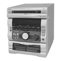
Provides overall technical data for the Hi-Fi component system.

Component Specifications

CD Player and Tuner Specifications

Specifications for CD player, AM, and FM tuner sections.

Section 1: Servicing Notes and Safety

Optical Pick-up and Laser Diode Handling

Precautions for handling optical components and laser diodes.

Component Replacement and Repair Guidelines

Notes on chip component replacement and flexible circuit board repair.

Model Identification

Installation and Initial Procedures

Disc Tray Opening and Rotary Encoder Installation

Instructions for opening the disc tray and installing the rotary encoder.

Section 2: General Information

Location of Controls Overview

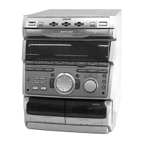
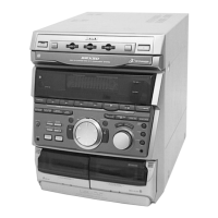
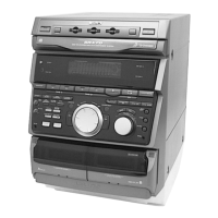
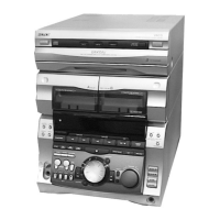
Identifies front panel controls and indicators.

Setting the System Clock

Section 3: Disassembly

Mechanism Deck Sections

Tape Mechanism Deck Details

Exploded view and notes for the tape mechanism deck.

CD Mechanism Deck Details

Exploded view and notes for the CD mechanism deck.

Main Board Assembly

Section 4: Test Mode Operations

System Reset and CD Delivery Modes

Procedures for MC reset, CD delivery, and sled servo modes.

Tuner Step and Indicator Light Test Modes

Modes for changing tuner steps and testing indicator lights.

Aging Mode Procedures

CD and Tape Deck Aging Mode Operation

Steps for executing aging mode for CD and tape deck sections.

Section 5: Mechanical Adjustments

Torque Measurement Standards

Specifications for torque measurement in tape drive operations.

Section 6: Electrical Adjustments

Playback Head Azimuth and Tape Speed Adjustments

Procedures for azimuth and tape speed adjustments.

Playback Level Adjustments

Procedure for adjusting playback output levels.

Tape Deck Recording Adjustments

REC Bias and Level Adjustments (Deck B)

Procedures for REC bias and level adjustments on deck B.

Tuner Section Adjustments

MW and FM Tuned Level Adjustments

Procedures for adjusting MW and FM tuned levels.

FM Polar Adjustment Procedure

CD Section Performance Checks

CD Section Waveform and Level Checks

Procedures for checking E-F balance, S-curve, and RF level.

Section 7: Diagrams and Board Locations

Circuit Boards Location Overview

Diagram showing the physical placement of circuit boards.

Tuner Section Block Diagram

CD Section Block Diagram

Tape Deck Section Block Diagram

Main Section Block Diagrams (Parts 1 & 2)

Display, Key Control, Power Supply Block Diagram

Notes on Diagrams and Schematics

Printed Wiring Board - Tuner Section

Schematic Diagram - Tuner Section

Printed Wiring Board - CD Section

Schematic Diagram - CD Section

Printed Wiring Boards - CD Motor Section

Schematic Diagram - CD Motor Section

Printed Wiring Board - Tape Deck Section

Schematic Diagram - Tape Deck Section

Printed Wiring Board - LEAF SW Section

Schematic Diagram - LEAF SW Section

Printed Wiring Board - Main Section

Schematic Diagram - Main Section (1/4)

Schematic Diagram - Main Section (3/4)

Printed Wiring Board - Panel Section

Schematic Diagram - Panel Section

Printed Wiring Board - CD-SW Section

Schematic Diagram - CD-SW Section

Printed Wiring Board - HP Section

Schematic Diagram - HP Section

Printed Wiring Boards - Power Amp Section

Schematic Diagram - Power Amp Section

Printed Wiring Board - Transformer Section

Schematic Diagram - Transformer Section

Waveform Analysis

TCB, BD, Main, and Panel Board Waveforms

Illustrates key waveforms for TCB, BD, Main, and Panel boards.

IC Block Diagrams

TCB Board IC Block Diagrams

Detailed block diagrams for ICs on the TCB board.

IC Circuit Diagrams

IC1701 and IC1702 Circuit Diagrams

Circuit diagrams for IC1701 (IR3R42) and IC1702 (µPD4053BC).

BD Board IC Block Diagram

BD Board IC Circuit Diagrams

IC102 and IC103 Circuit Diagrams

Circuit diagrams for IC102 (BA5941FP-E2) and IC103 (CXD2519Q).

Motor and Panel IC Circuit Diagrams

Motor and Panel IC Circuit Diagrams

Circuit diagrams for motor driver ICs and panel ICs.

IC Pin Function Descriptions

Main Board IC501 Pin Functions

Detailed pin functions for the main board IC501 (System Controller).

Main Board IC Pin Functions (Continued)

Continued pin function descriptions for main board ICs.

Panel Board IC601 Functions

Panel Board IC601 Pin Functions

Detailed pin functions for the panel board IC601.

Exploded Views and Hardware

Case Section Exploded View

Exploded view of the case section with part references.

Hardware List

List of hardware components like screws and rivets.

Front Panel Section Exploded View

Chassis Section Exploded View

Exploded View Parts Lists

Chassis and Transformer Parts List

Parts list for chassis, transformer, and related boards.

CD Mechanism Deck Section-1 Exploded View

CD Mechanism Deck Section-2 Exploded View

Base Unit Section Exploded View

Tape Mechanism Deck Section-1 Exploded View

Tape Mechanism Deck Section-2 Exploded View

Section 9: Electrical Parts List

Amplifier (L) Component List

Component list for the Amplifier (L) board.

Amplifier (R) Component List

Component list for the Amplifier (R) board.

Audio Board Component List

BD Board Component List

Panel, Sensor, and TCB Board Component Lists

Panel, Sensor, and TCB Board Components

Lists components for Panel, Sensor, and TCB boards.

Leaf SW and Main Board Component Lists

Leaf SW and Main Board Components

Lists components for Leaf SW and Main boards.

Main Board Component Lists (Continued)

Main Board Component Lists (Continued)

Main Board Component Lists (Continued)

Motor and Panel Component Lists

Motor and Panel Components

Lists components for motor assemblies and panel section.

Panel Component Lists (Continued)

Panel Component Lists (Continued)

Panel, Sensor, TCB Board Component Lists (Continued)

TCB Board Component Lists (Continued)

TCB Transformer Component Lists

Hardware and Miscellaneous Parts

Hardware List

List of hardware items like screws and rivets.

Miscellaneous Accessories

List of accessories and optional items.

Related product manuals