Do you have a question about the Sony HCD-GRX7J and is the answer not in the manual?
Detailed specifications for the amplifier section, including power output and distortion.
Specifications for amplifier section specific to different regional models.
Proper handling of optical pick-up and base unit to prevent damage.
Safety guidelines for checking the laser diode emission from the CD player.
Precautions for replacing chip components, emphasizing care with tantalum capacitors.
Guidelines for repairing flexible circuit boards, including soldering temperature limits.
Warning regarding hazardous radiation exposure if service procedures differ from specifications.
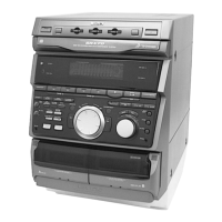
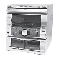
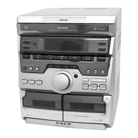
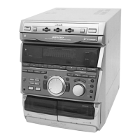
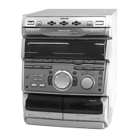
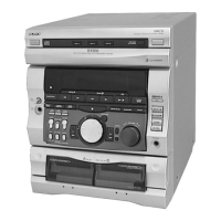
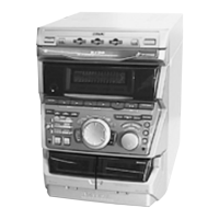
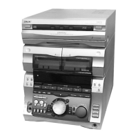
Identification of all controls and their locations on the unit.
Step-by-step instructions for setting the unit's clock time.
Instructions for removing the outer case and accessing internal components.
Procedures for detaching and removing the front panel assembly.
Resets system data to factory defaults or retains presets.
Modes for CD pickup transport durability and motor control.
Activates all LEDs and display for functional checks and button tests.
Sequence for aging mode checks and list of error codes with factors.
Essential precautions before performing mechanical adjustments on the unit.
Specific torque values and meter readings for tape deck mechanical adjustments.
Adjustments for the deck section, including azimuth, tape speed, and playback level.
Procedure for adjusting the azimuth of the record/playback heads for both decks.
Steps for adjusting tape speed on Deck B using test tapes and frequency counter.
Procedure for adjusting playback level on Deck A using test tapes and oscilloscope.
Procedure for adjusting recording bias on Deck B for optimal performance.
Procedure for adjusting recording level on Deck B for optimal performance.
Steps for adjusting the AM tuner section's tuned level.
Adjustments for the FM section, including tuned level and polar adjustments.
Procedure for FM polar adjustment specific to East European and CIS models.
Procedure for checking the S-curve waveform for proper CD tracking and focus.
Method for checking the RF signal level and waveform clarity for CD playback.
Procedure to check E-F balance and traverse waveform for CD mechanism operation.
Visual guide showing the placement of all circuit boards within the unit.
Block diagram illustrating the signal path for the tuner section in specific regional models.
Block diagram for the tuner section, specific to East European and CIS models.
Block diagram detailing the CD mechanism deck circuitry and signal flow.
Block diagram illustrating the functional blocks and signal paths of the tape deck.
Block diagram of the main control and processing section of the unit.
Block diagram covering display drivers, key input handling, and power supply circuits.
Detailed schematic of the tuner section for specific regional models.
Detailed schematic of the tuner section for East European and CIS models.
Printed wiring board layout for the CD section, showing component placement.
Detailed schematic diagram for the CD section, showing component interconnections.
Printed wiring board layouts for the CD motor control sections.
Schematic diagrams for the CD motor control circuits.
Printed wiring board layout for the tape deck section, showing component placement.
Detailed schematic diagram for the tape deck section, showing circuit interconnections.
Printed wiring board and schematic diagrams for the leaf switch section.
Printed wiring board layout for the main section of the unit.
Detailed schematic diagram for the main section, part 1 of 4.
Detailed schematic diagram for the main section, part 2 of 4.
Detailed schematic diagram for the main section, part 3 of 4.
Printed wiring board layout for the panel section, including controls and indicators.
Printed wiring board and schematic diagrams for the CD switch section.
Printed wiring board and schematic diagrams for the headphone jack section.
Printed wiring board layout for the power amplifier section.
Detailed schematic diagram for the power amplifier section.
Printed wiring board layout for the transformer section.
Schematic diagram for the transformer section.
Block diagrams for tuner section ICs LC72130 and LA1838.
Block diagram for IC101 (CXA1992AR) on the BD board, related to CD player functions.
Block diagrams for ICs on CD motor, panel, and audio boards.
Block diagram for IC601 (TMP87PM74F-6695) on the panel board.
Detailed pin function description for the main board's system controller IC501.
Exploded view of the case section, detailing parts like lids, panels, and screws.
Exploded view of the front panel section, showing controls, LEDs, and mounting hardware.
Exploded view of the chassis section, including boards, transformers, and wiring harnesses.
Exploded view of the CD mechanism deck, showing parts like brackets, trays, and motors.
Exploded view of the CD mechanism deck, showing parts like pulleys, gears, and covers.
Exploded view of the base unit (CD pick-up mechanism), detailing its parts and assembly.
Exploded view of the tape mechanism deck, showing heads, springs, and bases.
Exploded view of the tape mechanism deck, detailing motors, belts, and boards.
List of electrical parts used on the audio board.
List of electrical parts for the BD board, including components like capacitors and resistors.
List of electrical parts used on the main board, covering a wide range of components.
Parts list for the Headphone (HP) and Leaf Switch (SW) boards.
Further listing of electrical parts for the main board.
Additional electrical parts list entries for the main board.
More electrical parts for the main board, including resistors and transistors.
Final entries for the main board parts list, detailing resistors and transistors.
List of parts for the motor slide and motor turn sections.
Comprehensive list of electrical parts for the panel board.
Further listing of parts for the panel board, including resistors and transistors.
List of electrical parts for the power amplifier section.
Additional electrical parts for the power amplifier section.
List of electrical parts for the TCB board, including ICs, filters, and transistors.
Further listing of electrical parts for the TCB board, including resistors and jumpers.
Parts list for TCB section (resistors, jumpers) and Transformer section (fuses, resistors).
Additional parts list entries for the TCB board.
Further parts list entries for the transformer section.
List of miscellaneous items used in the assembly.
List of screws, washers, and other hardware used in the assembly.
| Brand | Sony |
|---|---|
| Model | HCD-GRX7J |
| Category | Stereo System |
| Language | English |