MICROFILM
SERVICE MANUAL
MINI Hi-Fi COMPONENT SYSTEM
US Model
AEP Model
UK Model
HCD-RXD9
E Model
HCD-GRX9900
SPECIFICATIONS
HCD-GRX9900/RXD9
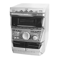
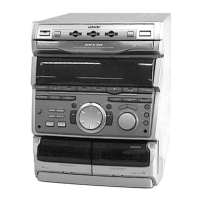
Photo: HCD-RXD9 (US model)
Dolby noise reduction manufactured under license
from Dolby Laboratories Licensing Corporation.
“DOLBY” and the double-D symbol a are trade-
marks of Dolby Laboratories Licensing Corporation.
HCD-GRX9900/RDX9 are the Amplifier,
CD player, Tape Deck and Tuner section
in MHC-GRX9900/RXD9.
Amplifier section
US model:
AEP and UK models:
DIN power output (rated) 120 + 120 watts
(8 ohms at 1 kHz, DIN)
Continuous RMS power output (reference)
150 + 150 watts
(8 ohms at 1 kHz, 10% THD)
Music power output (reference)
275 + 275 watts
(8 ohms at 1 kHz, 10% THD)
E models:
The following measured at AC 120, 220, 240 V 50/60 Hz
DIN power output (rated) 200 + 200 watts
(6 ohms at 1 kHz, DIN)
Continuous RMS power output (reference)
250 + 250 watts
(6 ohms at 1 kHz, 10% THD)
– Continued on next page –
Model Name Using Similar Mechanism NEW
CD Mechanism Type CDM38LH-5BD32L
Base Unit Name BU-5BD32L
Optical Pick-up Name KSS-213D/Q-NP
Model Name Using Similar Mechanism NEW
Tape Transport Mechanism Type TCM-230AWR2
CD
Section
Tape deck
Section