EasyManua.ls Logo

Sony HCD-GRX50 User Manual

Sony HCD-GRX50
71 pages
To Next Page IconTo Next Page
Page #1 background imageLoading...
Page #1 background image
MICROFILM
SERVICE MANUAL
MINI Hi-Fi COMPONENT SYSTEM
HCD-GRX50/R770/RXD7
Photo: HCD-GRX50
Dolby noise reduction manufactured under license
from Dolby Laboratories Licensing Corporation.
“DOLBY” and the double-D symbol a are trade-
marks of Dolby Laboratories Licensing Corporation.
Canadian Model
HCD-RXD7
AEP Model
HCD-R770/RXD7
UK Model
HCD-R770
E Model
Australian Model
HCD-GRX50
HCD-GRX50/R770/RXD7 are the Ampli-
fier, CD player, Tape Deck and Tuner
section in HMC-GRX50/R770/RXD7.
SPECIFICATIONS
Amplifier section
Canadian model:
Continuous RMS power output (reference)
70 + 70 watts
(6 ohms at 1 kHz, 10% THD)
Total harmonic distortion less than 0.07%
(6 ohms at 1 kHz, 45 W)
European and Russian models:
DIN power output (rated) 80 + 80 watts
(8 ohms at 1 kHz, DIN)
Continuous RMS power output (reference)
100 + 100 watts
(8 ohms at 1 kHz, 10% THD)
Music power output (reference)
170 + 170 watts
(6 ohms at 1 kHz, 10% THD)
Other models:
The following measured at AC 120, 220, 240 V 50/60 Hz
DIN power output (rated) 110 + 110 watts
(8 ohms at 1 kHz, DIN)
Continuous RMS power output (reference)
140 + 140 watts
(8 ohms at 1 kHz, 10% THD)
– Continued on next page –
Model Name Using Similar Mechanism NEW
CD Mechanism Type CDM38LH-5BD32L
Base Unit Name BU-5BD32L
Optical Pick-up Name KSS-213D/Q-NP
Model Name Using Similar Mechanism NEW
Tape Transport Mechanism Type TCM-230AWR2
CD
Section
Tape deck
Section
Question and Answer IconNeed help?

Do you have a question about the Sony HCD-GRX50 and is the answer not in the manual?

Sony HCD-GRX50 Specifications

General IconGeneral
BrandSony
ModelHCD-GRX50
CategoryStereo System
LanguageEnglish

Summary

Specifications

Amplifier Section Specs

Details RMS power output and THD for different models.

Safety Warnings

Safety-Related Component Warning

Alerts to critical components for safe operation.

Servicing Notes

Precautions for Repair (Optical, Laser, Components, Boards)

Precautions for handling optical pick-up, laser diode, components, and flexible boards.

Control Panel Overview

Front and Rear Panel Control Identification

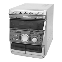
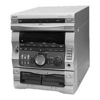
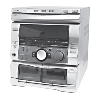
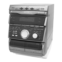
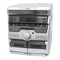
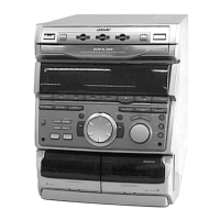
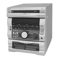
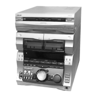
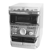
Identifies all controls on front and rear panels.

Setting the Time

Disassembly Procedures

Case & Loading Panel Removal Steps

Guides for removing the unit's case and loading panel.

Section Disassembly

Front Panel & CD Mechanism Removal

Steps to remove front panel and CD mechanism deck.

Board Removal Procedures

Tape Mechanism & Main Board Removal

Procedures for removing tape mechanism and main board.

Test Modes & Service Operations

Aging Mode Operations

Tape Deck Aging Mode

Adjustments - Mechanical & Electrical

Mechanical Precautions & Electrical Test Mode

Covers mechanical precautions and electrical test mode entry.

Tape Deck Adjustments

Azimuth, Speed, and Level Calibration

Procedures for azimuth, tape speed, and playback level adjustments.

Tape Deck Recording Adjustments

REC Bias & REC Level Calibration

Procedures for adjusting recording bias and level for Deck B.

CD Section Performance Checks

S-Curve, E-F Balance, RF Level Checks

Procedures for checking S-curve, E-F balance, and RF level.

Block Diagrams - CD Servo Section

CD Servo System Block Diagram

Shows the functional blocks of the CD servo system.

Block Diagrams - Tape Deck Section

Block Diagrams - Main Section

Block Diagrams - Display, Key, Power

Schematic Diagrams - BD Board

BD Board Detailed Schematic

Detailed schematic diagram of the BD board.

Schematic Diagrams - Audio Board

Audio Board Detailed Schematic

Detailed schematic diagram of the audio board.

Printed Wiring Boards - LEAF SW Board

Schematic Diagrams - MAIN Board (Part 1)

MAIN Board Schematic (1/4)

Detailed schematic of the main board, section 1/4.

Schematic Diagrams - MAIN Board (Part 2)

MAIN Board Schematic (2/4)

Detailed schematic of the main board, section 2/4.

Schematic Diagrams - MAIN Board (Part 3)

MAIN Board Schematic (3/4)

Detailed schematic of the main board, section 3/4.

Schematic Diagrams - MAIN Board (Part 4)

MAIN Board Schematic (4/4)

Detailed schematic of the main board, section 4/4.

Schematic Diagrams - PANEL Board

Printed Wiring Boards & Schematic - CD SW Board

Waveform Measurements

IC Block Diagrams - BD Board

IC Diagrams

IC Pin Function Descriptions

MAIN BOARD IC501 Pin Function Details

Details pin functions for IC501 on the main board.

MAIN BOARD IC501 Pin Function Details (Continued)

Continues pin function details for IC501.

MAIN BOARD IC501 Pin Function Details (Final)

Final pin function details for IC501.

Exploded Views - Front Panel

Exploded Views - CD Mechanism

Exploded Views - Base Unit

Exploded Views - Tape Mechanism Deck

Electrical Parts List - Audio Board

Electrical Parts List - Audio & BD Boards

Electrical Parts List - BD, CD SW, Connector, LEAF SW Boards

Electrical Parts List - LEAF SW & MAIN Boards

Electrical Parts List - MAIN Board

Electrical Parts List - Multiple Boards

Electrical Parts List - PANEL Board

Electrical Parts List - PANEL, SENSOR, SUB TRANS Boards

Electrical Parts List - SUB TRANS & TRANS Boards

Related product manuals