EasyManua.ls Logo

Sony HCD-RXD9 Service Manual

Sony HCD-RXD9
74 pages
To Next Page IconTo Next Page
Page #1 background imageLoading...
Page #1 background image
MICROFILM
SERVICE MANUAL
MINI Hi-Fi COMPONENT SYSTEM
US Model
AEP Model
UK Model
HCD-RXD9
E Model
HCD-GRX9900
SPECIFICATIONS
HCD-GRX9900/RXD9
Photo: HCD-RXD9 (US model)
Dolby noise reduction manufactured under license
from Dolby Laboratories Licensing Corporation.
“DOLBY” and the double-D symbol a are trade-
marks of Dolby Laboratories Licensing Corporation.
HCD-GRX9900/RDX9 are the Amplifier,
CD player, Tape Deck and Tuner section
in MHC-GRX9900/RXD9.
Amplifier section
US model:
AEP and UK models:
DIN power output (rated) 120 + 120 watts
(8 ohms at 1 kHz, DIN)
Continuous RMS power output (reference)
150 + 150 watts
(8 ohms at 1 kHz, 10% THD)
Music power output (reference)
275 + 275 watts
(8 ohms at 1 kHz, 10% THD)
E models:
The following measured at AC 120, 220, 240 V 50/60 Hz
DIN power output (rated) 200 + 200 watts
(6 ohms at 1 kHz, DIN)
Continuous RMS power output (reference)
250 + 250 watts
(6 ohms at 1 kHz, 10% THD)
– Continued on next page –
Model Name Using Similar Mechanism NEW
CD Mechanism Type CDM38LH-5BD32L
Base Unit Name BU-5BD32L
Optical Pick-up Name KSS-213D/Q-NP
Model Name Using Similar Mechanism NEW
Tape Transport Mechanism Type TCM-230AWR2
CD
Section
Tape deck
Section
Question and Answer IconNeed help?

Do you have a question about the Sony HCD-RXD9 and is the answer not in the manual?

Sony HCD-RXD9 Specifications

General IconGeneral
BrandSony
ModelHCD-RXD9
CategoryStereo System
LanguageEnglish

Summary

SERVICE MANUAL

Amplifier Section Specifications

Describes audio power specifications for US, AEP, and UK models.

General Specifications

Lists technical specifications for CD, Tape deck, and Tuner sections.

Detailed Specifications

Component and System Specifications

Details specifications for CD, tape, tuner, and general unit functions.

SECTION 1 SERVICING NOTES

Safety Procedures and Leakage Testing

Covers safety checks, AC leakage testing methods, and limits.

LASER PRODUCT SAFETY AND HANDLING

Optical Pick-Up, Diode, and Chip Component Notes

Precautions for optical pick-up, laser diode emission, and chip components.

DISC TRAY OPERATION AND INSTALLATION NOTES

Disc Tray Operation and Rotary Encoder Installation

Instructions for opening the disc tray and installing the rotary encoder.

SECTION 2 GENERAL

Control Locations (Front & Rear Panels)

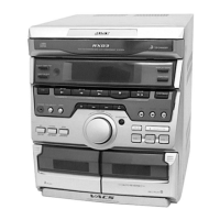
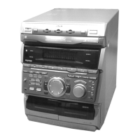
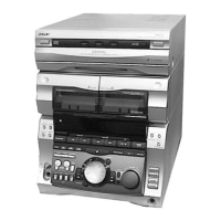
Identifies and labels controls on the front and rear panels of the unit.

Setting the Clock Time

Time Setting and Changing Procedures

Instructions for initial and subsequent clock time setting.

SECTION 3 DISASSEMBLY

Case and Loading Panel Disassembly

Step-by-step instructions for disassembling the case and loading panel.

FRONT PANEL AND CD MECHANISM SECTIONS

Front Panel and CD Mechanism Deck Removal

Steps for removing the front panel and CD mechanism deck.

TAPE MECHANISM DECK AND MAIN BOARD SECTIONS

Tape Mechanism Deck and Main Board Removal

Procedures for removing the tape deck and main board.

SECTION 4 TEST MODE

System Reset, Tuning, CD, and Diagnostic Modes

Covers reset, tuning interval, CD test/service, and diagnostic modes.

Aging Mode Operations and Displays

Aging Mode Sequences and CD Displays

Outlines aging sequences and CD section display formats.

Tape Deck Section Aging Mode Sequence

SECTION 5 MECHANICAL ADJUSTMENTS

Deck Section Adjustments and Torque Measurement

Procedures for deck mechanical adjustments and torque measurements.

Head Azimuth Adjustment

Procedure to adjust the azimuth of the record/playback heads.

DECK B and DECK A Adjustment Procedures

Tape Speed and Playback Level Adjustments

Procedures for adjusting tape speed (Deck B) and playback level (Deck A).

SECTION 6 ELECTRICAL ADJUSTMENTS

Deck Section Electrical Adjustments

Details electrical adjustments for the tape deck section.

Recording Bias and Level Adjustments

Procedures for adjusting recording bias and level on Deck B.

CD SECTION Adjustments

S-Curve, RF Level, and E-F Balance Checks

Procedures for S-curve, RF level, and E-F balance checks on the CD player.

SECTION 7 DIAGRAMS

CD SERVO Section Block Diagram

Block diagram illustrating the CD servo system circuitry.

TAPE DECK Section Block Diagram

MAIN Section Block Diagram

DISPLAY/KEY CONTROL/POWER SUPPLY Section Block Diagram

Notes on Diagrams and Boards

Diagram Conventions and Board Locations

Explains diagram symbols and shows circuit board locations.

7-6. PRINTED WIRING BOARD - BD Board

BD Board Layout (Sides A & B)

Printed wiring board layouts for the BD board (Sides A and B).

7-7. SCHEMATIC DIAGRAM - BD Board

7-8. PRINTED WIRING BOARDS - CD MOTOR Section

CD Motor Related Board Layouts

Printed wiring board layouts for CD motor related boards (Slide, Turn, Connector, Sensor).

7-9. SCHEMATIC DIAGRAM - CD MOTOR Section

7-10. PRINTED WIRING BOARD - AUDIO Board

7-11. SCHEMATIC DIAGRAM - AUDIO Board

LEAF SW Board Diagrams

LEAF SW Board Printed Wiring and Schematic

Printed wiring board layout and schematic diagram for the leaf switch board.

7-14. PRINTED WIRING BOARD - MAIN Board

MAIN Board Schematic Diagram (1/4)

MAIN Board Schematic Diagram (2/4)

MAIN Board Schematic Diagram (3/4)

MAIN Board Schematic Diagram (4/4)

PANEL/CD SW Board Diagrams

PANEL/CD SW Board Printed Wiring and Schematic

Printed wiring board layouts and schematic for panel/CD SW boards.

PANEL (1/3)/CD SW Board Schematic

PANEL (2/3) Board Schematic

PANEL (3/3) Board Schematic

TRANS Board Diagrams

TRANS Board Printed Wiring and Schematic

Printed wiring board layout and schematic diagram for the trans board.

SUB TRANS Board (RXD9) Diagrams

SUB TRANS Board (RXD9) Printed Wiring and Schematic

Printed wiring board layout and schematic diagram for the sub trans board (RXD9).

Waveforms and IC Block Diagrams

BD Board Waveforms and IC Block Diagram

Displays waveforms and IC block diagram for BD board ICs.

Main and Panel Board Waveforms

Displays waveforms for Main and Panel board ICs.

IC Block Diagrams

Motor Board IC Block Diagrams

IC block diagrams for Motor Turn and Motor Slide boards.

IC Block Diagrams

Audio and Panel Board IC Block Diagrams

IC block diagrams for Audio and Panel boards.

7-27. IC PIN FUNCTION DESCRIPTION

MAIN BOARD IC501 M30622MA-A07FP (SYSTEM CONTROLLER)

Pin function details for IC501 on the main board.

PANEL BOARD IC601 TMP88CS76F-6004 (FLUORESCENT INDICATOR TUBE DRIVER, KEY CONTROL)

SECTION 8 EXPLODED VIEWS

Case Section Exploded View

Exploded view and parts list for the case section.

Front Panel Section Exploded View

Exploded view and parts list for the front panel section.

Chassis Section Exploded View

CD Mechanism Deck Section-1 Exploded View

Exploded view of the CD mechanism deck section 1.

CD Mechanism Deck Section-1 Exploded View

CD Mechanism Deck Section-2 Exploded View

Base Unit Section Exploded View

Tape Mechanism Deck Section-1 Exploded View

Tape Mechanism Deck Section-2 Exploded View

SECTION 9 ELECTRICAL PARTS LIST

Audio Section Parts List

Lists electrical parts for the audio section, including capacitors, ICs, coils, transistors, and resistors.

Audio Board Parts List

Audio Board Resistors and Variable Resistors

Lists resistors and variable resistors for the audio board.

BD CD SW CONNECTOR LEAF SW Parts List

LEAF SW MAIN Parts List

MAIN Board Parts List

MAIN Board IC, Jack, Coil, Transistor, Resistor List

MAIN Board Resistor List

MAIN Board Resistor List

MAIN Board Resistor List

Motor and Panel Boards Parts List

PANEL Board Parts List

PANEL Board Transistor and Resistor List

PANEL SENSOR Parts List

SENSOR SUB TRANS TRANS Parts List

TRANS Board Parts List

MANUAL, INSTRUCTION List

Related product manuals