AEP Model
UK Model
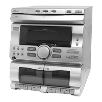
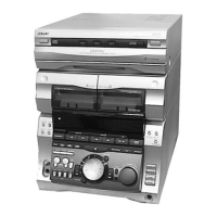
HCD-RX90
E Model
Australian Model
Tourist Model
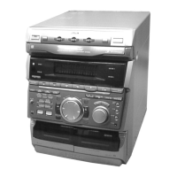
HCD-GR8
SERVICE MANUAL
HCD-GR8/RX90
HCD-GR8/RX90 is the tuner, deck, CD and
amplifier section in MHC-GR8/RX90.
Model Name Using Similar Mechanism HCD-GR7/RX70
CD Mechanism Type
CDM38L-5BD29AL
Base Unit Name BU-5BD29AL
Optical Pick-up Name
KSS-213D/Q-NP
Model Name Using
Similar Mechanism HCD-H881
Tape Transport Mechanism Type TCM-220WR2
CD
Section
Tape deck
Section
SPECIFICATIONS
* Dolby noise reduction manufactured
under license from Dolby Laboratories
Licensing corporation.
"DOLBY" and the double-D symbol a
are trademarks of Dolby Laboratories
Licensing Corporation.
Signal-to-noise ratio More than 90 dB
Dynamic range More than 90 dB
CD OPTICAL DIGITAL OUT
(Square optical connector jack, rear panel)
Wavelength 600 nm
Output Level –18 dBm
Tape player section
Recording system 4-track 2-channel stereo
Frequency response 60 – 13,000 Hz (±3 dB),
(DOLBY NR OFF) using Sony TYPE I casstte
60 – 14,000 Hz (±3 dB),
using Sony TYPE II cassette
Wow and flutter ±0.15% W.Peak (IEC)
0.1% W.RMS (NAB)
±0.2% W.Peak (DIN)
– Continued on next page –
Amplifier section
DIN power output (RX90)
80+80 watts
(8 ohms, at 1kHz, DIN)
Continuous RMS power output
RX90: 100+100 watts
(8ohms at 1kHz, 10% THD)
GR8: 90+90 watts
(8ohms at 1kHz, 10% THD)
Peak music power output
GR8: 1500 watts
Music power output
RX90: 160+160 watts
(8ohms at 1kHz, 10% THD)
Inputs VIDEO/MD IN (phono jacks):
voltage 250 mV, impedance
47 kilohms MIX MIC (phone
jack): sensitivity 1 mV,
impedance 10 kilohms
Outputs VIDEO/MD OUT (phone
jacks): voltage 250 mV
impedance 1 kilohms
PHONES (stereo phone jack):
accepts headphones of 8 ohms
or more.
SPEAKER:
accepts impedance of 8 to 16
ohms
SURROUND SPEAKER:
accepts impedance of 16
ohms.
SUPER WOOFER:
Voltage 1 V, impedance 1 kilo
ohm
CD player section
System Compact disc and digital
audio system
Laser Semiconductor laser
(λ=780 nm)
Emission duration: continuous
Laser output Max. 44.6 µW*
*This output is the value
measured at a distance of 200
mm from the objective lens
surface on the Optical Pick-up
Block with 7 mm aperture.
Frequency response 2 Hz – 20 kHz (±0.5 dB)
Wavelength 780 – 790 nm
Photo: HCD-RX90
MINI Hi-Fi COMPONENT SYSTEM
Ver 1.1 2002.06
9-960-881-12 Sony Corporation
2002F0500-1 Home Audio Company
C 2002.06 Published by Sony Engineering Corporation