Do you have a question about the Sony HCD-RX77S and is the answer not in the manual?
Technical details of the system's audio and component performance.
Details on the CD mechanism, laser, and output specifications.
Specifications for the tape deck recording and frequency response.
Details about FM, AM, and UKV tuner performance and ranges.
Covers power requirements, dimensions, and supplied accessories for various models.
Precautions for handling the optical pick-up and flexible boards.
Guidelines for safely checking the laser diode emission.
Advice on replacing chip components, especially tantalum capacitors.
Instructions for repairing flexible circuit boards, including soldering temperature.
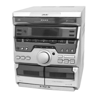
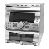
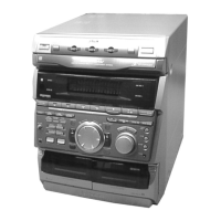
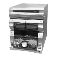
Identifies and labels all operational controls on the unit.
Resets the system to initial conditions, clearing RAM data.
Moves the pickup to a vibration-durable position for shipping after repair.
Resets the system while retaining preset data stored in memory.
Allows free running of the CD sled motor, useful for pickup cleaning.
How to change the AM tuner channel step between 9 kHz and 10 kHz.
Checks all LEDs and the fluorescent indicator tube, and tests button functions.
Specifies torque values for various tape deck mechanical adjustments.
Procedures for demagnetizing heads and performing tape deck adjustments.
Lists test tapes and their usage for adjustments.
Procedure for adjusting the head azimuth for both decks.
Procedure for adjusting the tape speed for Deck B.
Procedure for adjusting the playback level for Deck A.
Procedure for adjusting the recording bias for Deck B.
Procedure for adjusting the recording level for Deck B.
Procedure for tuning and adjusting the AM section.
Adjustments for the FM section, performed after AM adjustments.
Adjusts the TUNED indicator for the FM band.
Checks the symmetry and peak-to-peak level of the S-curve waveform.
Checks the clarity and signal level of the RF waveform.
Checks the E-F balance and traverse waveform for the CD mechanism.
Illustrates the location of various circuit boards within the unit.
Block diagram of the tuner section for specific European models.
Block diagram of the tuner section for East European and CIS models.
Schematic diagram of the tuner section for AEP, UK, German models.
Printed wiring board layout for the tuner section (AEP, UK, German models).
Printed wiring board layout for the tuner section (East European, CIS models).
Schematic diagram of the tuner section for East European, CIS models.
Printed wiring board layout for the CD section (BD Board).
Schematic diagram of the CD section (BD Board).
Printed wiring board layout for the Audio board related to the tape deck.
Schematic diagram for the Audio board related to the tape deck.
Printed wiring board layout for the Leaf SW section.
Schematic diagram for the Leaf SW section.
Printed wiring board layout for the Main section (Part 1/4).
Schematic diagram of the Main section (Part 1/4).
Schematic diagram of the Main section (Part 2/4).
Schematic diagram of the Main section (Part 3/4).
Printed wiring board layout for the CD-SW section.
Schematic diagram for the CD-SW section.
Printed wiring board layout for the HP section.
Schematic diagram for the HP section.
Printed wiring board layout for the Transformer section.
Schematic diagram for the Transformer section.
Block diagram for IC101 (CXA1992AR) on the BD board.
Block diagram for IC701 (M54641L) on the Motor (Turn) Board.
Block diagram for IC603 (BA3833F-E2) on the Panel Board.
Block diagram for IC801 (BA6286N) on the Motor (Slide) Board.
Block diagram for IC602 (μPC1330HA) on the Audio Board.
Pin function descriptions for IC501 (System Controller) on the Main Board.
Pin function description for IC601 (TMP87PM74F-6695) on the Panel Board.
| Audio Channels | 2.0 |
|---|---|
| CD Player | Yes |
| Remote Control | Yes |
| Type | Stereo System |
| Tuner | FM/AM |
| Connectivity | Audio input |
| Functions | CD Player, Radio, Cassette Deck |