EasyManua.ls Logo

Sony HCD-RX77 Service Manual

Sony HCD-RX77
86 pages
To Next Page IconTo Next Page
Page #1 background imageLoading...
Page #1 background image
MICROFILM
SERVICE MANUAL
MINI Hi-Fi COMPONENT SYSTEM
Canadian Model
HCD-RX77
AEP Model
HCD-R700/RX77/RX77S
UK Model
HCD-R700/RX77S
E Model
HCD-GRX7/GRX7J
Australian Model
HCD-GRX7
Tourist Model
HCD-GRX7J
Model Name Using Similar Mechanism HCD-H991AV
CD Mechanism Type
CDM38L-5BD29AL/
CDM38LH-5BD29AL
Base Unit Type BU-5BD29AL
Optical Pick-up Type KSS-213D/Q-NP
Model Name Using Similar Mechanism NEW
Tape Transport Mechanism Type
TCM-230AWR1/
230PWR1
HCD-GRX7/GRX7J/R700/
RX77/RX77S
HCD-GRX7/GRX7J/R700/RX77/RX77S
are the Amplifier, CD player, Tape Deck
and Tuner section in MHC-GRX7/
GRX7J/R700/RX77/RX77S.
Photo: HCD-RX77
Dolby noise reduction manufactured under license
from Dolby Laboratories Licensing Corporation.
“DOLBY” and the double-D symbol a are trade-
marks of Dolby Laboratories Licensing Corporation.
CD
Section
TAPE
DECK
Section
SPECIFICATIONS
Amplifier section
Canadian model:
Continuous RMS power output (reference)
100 + 100 watts
(8 ohms at 1 kHz, 10% THD)
Total harmonic distortion less than 0.07%
(8 ohms at 1 kHz, 55 W)
European and Russian models:
DIN power output (rated) 60 + 60 watts
(6 ohms at 1 kHz, DIN)
Continuous RMS power output (reference)
80 + 80 watts
(6 ohms at 1 kHz, 10% THD)
Music power output (reference)
135 + 135 watts
(6 ohms at 1 kHz, 10% THD)
Other models:
The following measured at AC 110, 220 V 50/60 Hz
DIN power output (rated) 85 + 85watts
(8 ohms at 1 kHz, DIN)
Continuous RMS power output (reference)
110 + 110 watts
(8 ohms at 1 kHz, 10% THD)
The following measured at AC 120, 240 V 50/60 Hz
DIN power output (rated) 105 + 105 watts
(8 ohms at 1 kHz, DIN)
Continuous RMS power output (reference)
130 + 130 watts
(8 ohms at 1 kHz, 10% THD)
Peak music power output (reference)
1500 watts
– Continued on next page –

Table of Contents

Question and Answer IconNeed help?

Do you have a question about the Sony HCD-RX77 and is the answer not in the manual?

Sony HCD-RX77 Specifications

General IconGeneral
TypeStereo System
Power Output100 W
Audio Channels2.0
CD PlayerYes
Cassette DeckYes
Remote ControlYes
Speakers2
BluetoothNo
USB PortNo
TunerAM/FM

Summary

Service Manual Overview

Specifications Summary

Details technical specifications including power output, distortion, and impedance.

Servicing Notes

Handling Optical Pick-up Block

Precautions for handling the optical pick-up block to prevent electrostatic damage.

Laser Diode Emission Check

Guidelines for safely checking laser diode emission from the optical pick-up block.

Safety-Related Component Warning

General Information

Location of Controls Overview

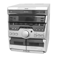
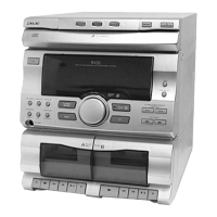
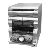
Identifies buttons and controls on the front panel of the unit.

Setting the Clock Time

Disassembly Procedure

Case Disassembly

Details the screws and steps for removing the outer case.

Front Panel Section Disassembly

Describes how to remove the front panel section, including disc tray and claws.

Test Modes

MC Cold Reset Mode

Clears all data including preset data in RAM to initial conditions.

CD Delivery Mode

Moves the pickup to a position durable to vibration for shipping.

Mechanical Adjustments

Mechanical Adjustments Precautions

Important precautions before performing mechanical adjustments.

Electrical Adjustments

Head Azimuth Adjustment

Procedure to adjust head azimuth for both decks using a test tape.

Deck B Tape Speed Adjustment

Tuner Section Adjustments

AM Tuned Level Adjustment

Procedure to adjust RV41 on the TCB board for the AM tuned level.

FM Tuned Level Adjustment

Procedure to adjust RV42 on the TCB board for the FM tuned indicator.

CD Section Checks

CD S-Curve Check

Procedure to check the S-curve waveform for symmetry and peak level.

Diagrams Overview

Circuit Board Locations

Diagram showing the placement of all major circuit boards.

Tuner Section Block Diagram (AEP/UK/DE)

CD Mechanism Deck Block Diagram

Tape Deck Section Block Diagram

Main Section Block Diagram

Display, Key Control, Power Supply Block Diagram

Notes on Diagrams and Boards

Schematic Diagram Notes

Explains conventions for capacitors, resistors, and internal components in schematics.

CD Section Printed Wiring Board

CD Section Schematic Diagram

CD Section Schematic Notes

Notes on conditions for voltage/waveform measurements and critical components.

Tape Deck Section Printed Wiring Board

Tape Deck Section Schematic Diagram

Tape Deck Schematic Notes

Notes on voltage and waveform measurement conditions for playback and recording.

LEAF SW Section Printed Wiring Board

Leaf SW Semiconductor Locations

Table listing semiconductor reference numbers and their locations on the LEAF SW board.

Main Section Printed Wiring Board

Main Section Schematic (1/4)

Main Schematic Notes (1/4)

Notes on voltage and waveform measurement conditions for FM and CD signals.

Main Section Schematic (2/4)

Main Section Schematic (3/4)

Main Section Schematic (4/4)

Panel Section Printed Wiring Board

Panel Semiconductor Locations

Table listing semiconductor reference numbers and their locations on the PANEL board.

Panel Section Schematic Diagram

CD-SW Section Printed Wiring Board

CD-SW Section Schematic Diagram

HP Section Printed Wiring Board

HP Section Schematic Diagram

Power Amp Section Printed Wiring Board

Power Amp Semiconductor Locations

Table listing semiconductor reference numbers and their locations on the POWER AMP board.

Power Amp Section Schematic Diagram

Transformer Section Printed Wiring Board

Transformer Section Schematic Diagram

IC Block Diagrams (TCB Board)

IC1701 IR3R42 Block Diagram (EE/CIS)

BD Board IC101 CXA1992AR Block Diagram

IC103 CXD2519Q Block Diagram

Motor (Turn) Board IC701 M54641L Block Diagram

IC Pin Function Description (Main Board IC501)

IC Pin Functions (Continued)

Disc Tray Turn Motor Control

Explains the control signals for the disc tray turn motor (M701).

Panel Board IC601 Pin Functions

Exploded Views Overview

Exploded View Notes

Notes on standardized parts, color indications, and non-supplied parts.

CD Mechanism Deck Section 1 Exploded View

Electrical Parts List (Audio Board)

Electrical Parts List (Main Board Capacitors)

Electrical Parts List (Main Board Diodes/ICs/Connectors)

Electrical Parts List (Main Board Transistors/Resistors)

Electrical Parts List (Power Amp Components)

Miscellaneous Parts List

Related product manuals