EasyManua.ls Logo

Sony HCD-RX55 User Manual

Sony HCD-RX55
54 pages
To Next Page IconTo Next Page
Page #1 background imageLoading...
Page #1 background image
HCD-GRX3/RX55/R300
US Model
Canadian Model
HCD-RX55
E Model
HCD-GRX3/R300
Australian Model
HCD-GRX3
SERVICE MANUAL
MINI Hi-Fi COMPONENT SYSTEM
HCD-GRX3/RX55/R300 are the tuner, deck,
CD and amplifier section in MHC-GRX3/
RX55/R300.
SPECIFICATIONS
Model Name Using Similar Mechanism HCD-G101
CD Mechanism Type CX3
Base Unit Type KSM-213BCM
Optical Pick-up Type KSS-213B/S-N
Model Name Using Similar Mechanism NEW
CWB44RR10
CD
SECTION
TAPE DECK
SECTION
Tape Transpor Mechanism Type
Sony Corporation
Home Audio Company
Published by Sony Engineering Corporation
9-922-804-12
2001K1600-1
© 2001.11
AUDIO POWER SPECIFICATIONS:
(U.S.A. model only)
POWER OUTPUT AND TOTAL HARMONIC DISTORTION:
with 6 loads both channels driven, from 70 – 20,000 Hz; rated 35 W per
channel minimum RMS power, with no more than 0.9% total harmonic
distortion from 250 mW to rated output.
Amplifier section
North American model
Continuous RMS power output
50 W + 50 W (6 at 1 kHz, 10% THD)
Other models
The following measured at AC 110, 220 V 60 Hz;
DIN power output (Rated) 35 W + 35 W (6 at 1 kHz, DIN)
Continuous RMS power output (Reference)
45 W + 45W (6 at 1 kHz, 10% THD)
The following measured at AC 120, 240 V 60 Hz;
DIN power output (Rated) 40 W + 40 W (6 at 1 kHz, DIN)
Continuous RMS power output (Reference)
50 W + 50W (6 at 1 kHz, 10% THD)
Peak music power output (Reference)
600 W
Inputs
MD IN (phone jacks) : voltage 450 mV, impedance 47 k
Outputs
MD OUT (phone jacks) : voltage 250 mV, impedance 1 k
PHONES (stereo phone jack) :
accepts headphones of 8 or more
SPEAKER : accepts impedance of 6 to 16
CD player section
System Compact disc and digital audio system
Laser Semiconductor laser (λ = 780 nm)
Emission duration: continuous
Laser output Max. 44.6 µW*
*This output is the value measured at a
distance of 200 mm from the objective
lens surface on the Optical Pick-up Block
with 7 mm aperture.
Frequency response 20 Hz – 20 kHz (± 0.5 dB)
Wavelength 780 – 790 nm
DIGITAL OUT (OPTICAL)
(Square optical connector jack, rear panel)
Wavelength 600 nm
Output Level –18 dBm
Tape deck section
Recording system 4 -track 2 -channel stereo
Frequency response 40 – 13,000 Hz (± 3dB), using Sony
TYPE Ι cassette
photo : HCD-GRX3
— Continued on next page —
Ver 1.1 2001. 11
Question and Answer IconNeed help?

Do you have a question about the Sony HCD-RX55 and is the answer not in the manual?

Sony HCD-RX55 Specifications

General IconGeneral
BrandSony
ModelHCD-RX55
CategoryStereo System
LanguageEnglish

Summary

SPECIFICATIONS

Audio Power Specifications

Details power output and total harmonic distortion for US and other models.

CD Player Section Specifications

Lists specifications for the CD player, including system, laser, and frequency response.

Tape Deck Section Specifications

Provides specifications for the tape deck, including recording system and frequency response.

SERVICING NOTES

Handling Optical Pick-Up Block or Base Unit

Provides guidelines for handling the optical pick-up block and base unit during repairs.

Laser Diode Emission Check

Instructions for checking laser diode emission, emphasizing safety precautions.

SAFETY CHECK-OUT PROCEDURES

AC Leakage Measurement

Details methods for measuring AC leakage current from exposed metal parts to ground.

SECTION 1 GENERAL

Location of Parts and Controls

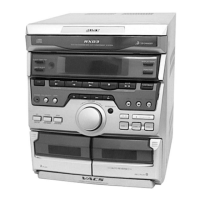
Illustrates and labels the various parts and controls on the unit's front panel.

SECTION 2 DISASSEMBLY

Upper Cover and CD Door Removal

Step-by-step instructions for removing the upper cover and CD door.

Front Panel Removal

Procedures for disassembling and removing the front panel.

SECTION 3 MECHANICAL ADJUSTMENTS

Torque Measurement

Details the procedure and specifications for measuring torque for FWD and FF/REW functions.

SECTION 4 ELECTRICAL ADJUSTMENTS

Record/Playback Head Azimuth Adjustment

Guides for adjusting the azimuth of the record/playback head for optimal sound quality.

Tape Speed Adjustment (Deck A)

Procedure for adjusting the tape speed for Deck A, including sample values.

TUNER SECTION ELECTRICAL ADJUSTMENTS

AM Tuning Voltage Adjustment

Procedure to adjust AM tuning voltage for optimal reception.

AM Tracking Adjustment

Steps to adjust AM tracking for accurate tuning across the band.

FM Tuning Voltage Adjustment

Procedure to adjust FM tuning voltage for optimal reception.

CD SECTION ELECTRICAL ADJUSTMENTS

RF Level Check

Procedure to check the RF signal level on the CD decoder board.

Focus Bias Adjustment

Steps to adjust the focus bias on the CD decoder board.

Focus Gain Adjustment

Notes that focus gain adjustment is optional and should be performed only if necessary.

SECTION 5 DIAGRAMS

Circuit Boards Location

Diagram showing the physical location of all circuit boards within the unit.

Block Diagrams - Deck Section

Block diagram illustrating the signal flow and components of the deck section.

Tuner/CD Section Diagram

Schematic diagram for the tuner and CD sections of the unit.

Printed Wiring Board - CD Section

Shows the component layout on the CD section's printed wiring board.

Schematic Diagram - CD Section

Detailed schematic diagram for the CD section, including component values.

Schematic Diagram - Panel Section

Detailed schematic diagram for the panel section, showing controls and display circuits.

Printed Wiring Board - Panel Section

Diagram illustrating the component layout on the panel section's printed wiring board.

Printed Wiring Board - Deck Section

Shows the component layout on the deck section's printed wiring board.

Schematic Diagram - Deck Section

Detailed schematic diagram for the deck section, illustrating tape playback and recording circuitry.

Schematic Diagram - Main Section

Detailed schematic diagram for the main section, covering tuner and amplifier circuits.

Printed Wiring Board - Main Section

Diagram showing the component layout on the main section's printed wiring board.

Printed Wiring Board - Amp Section

Diagram illustrating the component layout on the amplifier section's printed wiring board.

IC Pin Function - Panel Board

Table detailing the pin functions for IC601 (µPD78020SGF-043-3BA) on the Panel Board.

SECTION 6 EXPLODED VIEWS

Cabinet Section Exploded View

Exploded view of the unit's cabinet, listing part numbers and descriptions.

Front Panel Section Exploded View

Exploded view of the front panel, detailing parts and their locations.

Cassette Mechanism Deck Section Exploded View

Exploded view of the cassette mechanism deck, showing components and part numbers.

CD Mechanism Deck Section 1 Exploded View

Exploded view of the first part of the CD mechanism deck, listing components.

CD Mechanism Deck Section 2 Exploded View

Exploded view of the second part of the CD mechanism deck, showing components and part numbers.

Base Unit Section Exploded View

Exploded view of the base unit section, detailing components and part numbers.

SECTION 7 ELECTRICAL PARTS LIST

Amplifier Section Parts List

List of electrical parts for the amplifier section, including part numbers and descriptions.

CD Button and CD Decoder Parts List

Lists electrical parts for the CD button and CD decoder sections.

Deck Section Parts List

Lists electrical parts for the deck section, including resistors, transistors, and capacitors.

Deck Section Parts List (Continued)

Continues the list of electrical parts for the deck section.

Deck Section Parts List (Resistors and Transistors)

Lists resistors and transistors for the deck section.

MAIN SECTION ELECTRICAL PARTS LIST

Motor (6P)(S) and Panel Parts List

Lists electrical parts for the motor and panel sections.

Main Section Electrical Parts List (Capacitors, Filters, ICs)

Lists capacitors, filters, diodes, ICs, and connectors for the main section.

Main Section Electrical Parts List (Inductors, Transistors, Resistors)

Lists inductors, transistors, and resistors for the main section.

Main, Motor, and Panel Parts List (Resistors, Switches)

Lists resistors, switches, transformers, and motors for main, motor, and panel sections.

Panel Section Electrical Parts List (Capacitors, ICs, LEDs)

Lists capacitors, ICs, coils, LEDs, and transistors for the panel section.

Panel, Sensor, and Switch Parts List

Lists resistors, switches, sensors, and vibrators for panel and switch boards.

VOLUME SECTION PARTS LIST

Volume Control Parts List

Lists parts for the volume control section, including resistors, switches, and hardware.

CORRECTION-1

Correction of Electrical Parts

Provides corrections to electrical parts listed in the service manual.

PARTS LIST CORRECTIONS

Capacitor, Diode, IC, and Connector Corrections

Lists incorrect and correct part numbers for capacitors, diodes, ICs, and connectors.

SUPPLEMENT-1

AR Model and HCD-R300 Model Updates

Details additions and corrections for AR model and HCD-R300, referring to previous manuals.

Mechanical Parts List Updates

Lists updated part numbers for the mechanical parts list.

Electrical Parts, Miscellaneous, and Accessories Updates

Lists updates for electrical parts, miscellaneous items, and accessories.

REVISION HISTORY

Related product manuals