EasyManua.ls Logo

Sony HCD-RX9 Service Manual

Sony HCD-RX9
101 pages
To Next Page IconTo Next Page
Page #1 background imageLoading...
Page #1 background image
Sony Corporation
Home A&V Products Company
MHC-GRX8/R800/RX88/RX99
HCR-GRX8/R800/RX99
SERVICE MANUAL
MICROFILM
9-922-784-11
98B001671-1
Printed in Japan ©1998.2
Published by General Engineering Dept.
(Shibaura)
MHC-GRX8/R800/RX88/RX99 is composed of following
models.
As for the service manual, it is issued for each component
model, then, please refer to it.
AEP Model
UK Model
MHC-RX88/RX99
E Model
MHC-GRX8/R800
Australian Model
MHC-GRX8
PARTS LIST
Ref.No. Part No. Description Remark
–––––– ––––––– ––––––––– ––––––
ACCESSORIES & PACKING MATERIALS
********************************
1-475-571-11 COMMANDER, STANDARD (RM-SR8)
1-501-374-11 ANTENNA, LOOP
1-501-659-41 ANTENNA (FM) (GRX8/R800)
1-501-804-11 ANTENNA (FM) (RX88/RX99)
1-769-317-11 CORD, SPEAKER (2.5m) (FRONT SPEAKER)
1-769-433-11 CORD, SPEAKER(10m) (SURROUND SPEAKER)
3-862-011-11 MANUAL, INSTRUCTION (ENGLISH)
(EXCEPT G, TH)
3-862-011-21 MANUAL, INSTRUCTION (FRENCH, SPANISH)
(AEP, E, SP, MY, MX, AR, EA3)
3-862-011-31 MANUAL, INSTRUCTION (CHINESE)
(E, SP, MY, HK, TW)
3-862-011-41 MANUAL, INSTRUCTION (ARABIC) (EA3)
3-862-011-51 MANUAL, INSTRUCTION (GERMAN) (AEP, G)
MINI Hi-Fi COMPONENT SYSTEM
SPECIFICATIONS
Abbreviation
G : German model
EE : East European model
SP : Singapore model
MY : Malaysia model
MX : Mexican model
AR : Argentine model
EA3 : Saudi Arabia model
HK : Hong kong model
TW : Taiwan model
TH : Thai model
HCR-GRX8 is composed of HCD-GRX8 and SS-SR110
HCR-R800 is composed of HCD-R800 and SS-SR110
HCD-RX99 is composed of HCD-RX99 and SS-SR110
COMPONENT MODEL NAME FOR MHC-GRX8/R800/RX88/RX99
MHC-GRX8 MHC-R800 MHC-RX88 MHC-RX99
COMPACT DISC DECK
RECEIVER SYSTEM
HCD-GRX8 HCD-R800 HCD-RX88 HCD-RX99
FRONT SPEAKER SYSTEM SS-GRX8 SS-R800 SS-RX88 SS-RX99
SURROUND SPEAKER SYSTEM SS-SR110 SS-SR110
General
Power requirements
European models: 230 V AC, 50/60 Hz
Other models: 120 V, 220 V or 230 - 240 V AC, 50/60 Hz.
Adjustable with the voltage selector
Power consumption
MHC-GRX8/R800: 270 watts
MHC-RX88/RX99: 240 watts
Supplied accessories
AM loop antenna (1)
Remote RM-SR8
Batteries (2)
FM lead antenna (1)
Speaker cords (4)
Front speaker pads (8)
Design and specifications are subject to change without notice.
3-862-011-61 MANUAL, INSTRUCTION
(DUTCH, ITALIAN, PORTUGUESE) (AEP)
3-862-011-71 MANUAL, INSTRUCTION
(DANISH, FINNISH, SWEDISH) (AEP)
3-862-011-81 MANUAL, INSTRUCTION (POLISH, RUSSIAN)
(AEP, EE, CIS)
3-862-012-11 MANUAL, INSTRUCTION (HUNGARIAN)
(AEP,EE,CIS)
3-862-012-21 MANUAL, INSTRUCTION (CZECH) (AEP)
3-862-012-31 MANUAL, INSTRUCTION (GREEK) (AEP)
3-862-012-41 MANUAL, INSTRUCTION (TURKISH) (AEP)
3-862-015-31 MANUAL, INSTRUCTION (ENGLISH, THAI) (TH)
3-862-818-11 MANUAL, INSTRUCTION (ENGLISH, FRENCH,
GERMAN, SWEDISH, RUSSIAN)
(For SS-RX88/RX99)
4-991-151-21 COVER, BATTERY (FOR RM-SR8)
Ref.No. Part No. Description Remark
–––––– ––––––– ––––––––– ––––––
www.DataSheet4U.com

Table of Contents

Question and Answer IconNeed help?

Do you have a question about the Sony HCD-RX9 and is the answer not in the manual?

Sony HCD-RX9 Specifications

General IconGeneral
Power Output100 W
CD PlayerYes
Tuner BandsFM/AM
USB PlaybackYes
Output Power100 W
CD Player TypeSingle Disc
Cassette DeckYes
Audio Output Power100 W
Remote ControlYes
BluetoothNo
TypeStereo System
FunctionsCD, USB, FM/AM Tuner
Speakers2 Speakers

Summary

Specifications

Supplied Accessories

Lists items included with the product.

Abbreviation

Lists abbreviations used in the manual.

Specifications

CD Section Specifications

Details specifications for the CD playback section.

Tape Deck Section Specifications

Details specifications for the tape deck sections.

AM Tuner Section

Tuning Range and Band Types

Specifies tuning frequency ranges and band types for AM.

Safety Precautions

General Caution

Warns about hazardous radiation exposure from improper use.

Chip Component Replacement Notes

Advises on handling and replacing chip components.

Flexible Circuit Board Repairing Guidelines

Provides guidelines for soldering flexible circuit boards.

Optical Pick-up Handling Notes

Electrostatic Discharge Warning

Warns about ESD affecting the optical pick-up.

Flexible Board Handling Caution

Caution regarding handling flexible circuit boards.

Laser Diode Operation Checks

Laser Diode Emission Check

Guidance for safely checking laser diode output.

S-Curve Check Procedure

Steps for checking S-curve waveform for laser operation.

Servicing Notes

Disc Tray Opening Procedure

How to open the disc tray when the power is off.

General Overview

Front Panel Controls

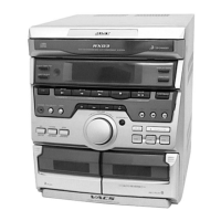
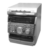
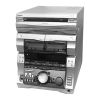
Identification of controls and parts on the front panel.

Disassembly Procedures

Loading Panel Disassembly

Steps to disassemble the loading panel.

Front Panel Disassembly

Steps to disassemble the front panel assembly.

Cassette Mechanism Deck Disassembly

Procedure for disassembling the cassette mechanism.

Panel Board and Cont Com Board Disassembly

Steps for removing panel and control boards.

Disc Tray Disassembly

Procedure for removing the disc tray.

Servicing Notes

Disc Tray Opening Procedure

Steps for opening the disc tray when the unit is powered off.

Installation Notes

Rotary Encoder Installation

Guidance for installing the rotary encoder correctly.

Location of Parts and Controls

Front Panel Controls Overview

Identifies and explains the function of front panel controls.

Disassembly Procedures

Loading Panel Disassembly

Detailed steps for disassembling the loading panel.

Front Panel Disassembly

Detailed steps for disassembling the front panel.

Disassembly Procedures

Cassette Mechanism Deck Disassembly

Procedure for removing the cassette mechanism deck.

Panel Board and Cont Com Board Disassembly

Steps to remove panel and control boards.

Disassembly Procedures

Disc Tray Disassembly

Steps for removing and handling the disc tray.

Service Mode Procedures

MC Cold Reset

Steps to reset the unit to initial conditions.

CD Delivery Mode

Mode for moving the CD pick-up for shipping.

MC Hot Reset

Steps to reset while retaining preset data.

Sled Servo Mode

Mode for running the CD sled motor freely.

AM Tuner Step Change-over

Procedure to switch AM channel steps between 9kHz and 10kHz.

Key Check Mode

Mode to check all LEDs and fluorescent indicator tube.

Service Mode Procedures

Aging Mode Operation

Procedure for checking CD player and tape deck operations.

Aging Mode Status Display

Explains how aging status is displayed.

Aging Mode CD Player Display

Details CD player aging status indicators.

Aging Mode Error Displays

Lists and explains error messages during aging.

Service Mode Procedures

Aging Mode Tape Deck Operations

Describes tape deck operations during the aging mode.

Mechanical Adjustments

Torque Measurement Specifications

Table of torque specifications for various parts.

Electrical Adjustments

Deck Section Azimuth Adjustment

Procedure for adjusting playback head azimuth.

Electrical Adjustments

Tape Speed Adjustment (Deck A)

Procedure for adjusting tape speed on Deck A.

Playback Level Adjustment (Deck A & B)

Procedure for adjusting playback levels for both decks.

Electrical Adjustments

Record Bias Adjustment (Deck B)

Procedure for adjusting record bias on Deck B.

Record Level Adjustment (Deck B)

Procedure for adjusting record level on Deck B.

Tuner Section Adjustments

AM Tuned Level Adjustment

Procedure for tuning AM reception levels.

FM Tuned Level Adjustment

Procedure for tuning FM reception levels.

Tuner Section Adjustments

FM Polar Adjustment

Procedure for FM polar adjustment in specific models.

CD Section Checks

S Curve Check

Steps to check CD S-curve waveform.

RF Level Check

Steps to check RF signal level for CD playback.

E-F Balance (Traverse) Check

Steps to check E-F balance for CD traverse.

Diagrams

Circuit Boards Location

Diagram showing the physical location of circuit boards.

Diagrams

Tuner Section Block Diagram (AEP, UK, German Model)

Block diagram for the tuner section in specific models.

Diagrams

Tuner Section Block Diagram (East European, CIS Model)

Block diagram for the tuner section in specific models.

Diagrams

CD Section Block Diagram

Block diagram illustrating the CD playback circuitry.

Diagrams

Deck Section Block Diagram

Block diagram for the tape deck sections.

Diagrams

Main Section Block Diagram

Block diagram of the main processing and control sections.

Diagrams

Power Section Block Diagram

Block diagram for the power supply and amplification circuits.

Diagrams

Display Section Block Diagram

Block diagram for the display control and indicators.

Waveforms

CD Section Waveforms

Illustrates waveforms for CD section tests.

Tuner Section Waveforms

Illustrates waveforms for tuner section adjustments.

Display Section Waveforms

Illustrates waveforms for display section signals.

Main Section Waveforms

Illustrates waveforms for main section signals.

Printed Wiring Boards

CD Section Printed Wiring Board

Layout of components on the CD section PWB.

Schematic Diagrams

CD Section Schematic Diagram

Electrical schematic for the CD section.

Schematic Diagrams

Tuner Section Schematic Diagram (AEP, UK, German Model)

Electrical schematic for the tuner section in specific models.

Printed Wiring Boards

Tuner Section Printed Wiring Board (AEP, UK, German Model)

Component layout for tuner section PWB in specific models.

Printed Wiring Boards

Tuner Section Printed Wiring Board (East European, CIS Model)

Component layout for tuner section PWB in specific models.

Schematic Diagrams

Tuner Section Schematic Diagram (East European, CIS Model)

Electrical schematic for the tuner section in specific models.

Schematic Diagrams

Deck Section Schematic Diagram

Electrical schematic for the tape deck mechanisms.

Printed Wiring Boards

Deck Section Printed Wiring Board

Component layout for the deck section PWB.

Printed Wiring Boards

Main Section Printed Wiring Board

Component layout for the main section PWB.

Schematic Diagrams

Main Section Schematic Diagram (1/4)

Electrical schematic for the main section (part 1 of 4).

Schematic Diagrams

Main Section Schematic Diagram (2/4)

Electrical schematic for the main section (part 2 of 4).

Schematic Diagrams

Main Section Schematic Diagram (3/4)

Electrical schematic for the main section (part 3 of 4).

Schematic Diagrams

Main Section Schematic Diagram (4/4)

Electrical schematic for the main section (part 4 of 4).

Schematic Diagrams

Mic/HP Section Schematic Diagram

Electrical schematic for the microphone and headphone sections.

Printed Wiring Boards

Mic/HP Section Printed Wiring Board

Component layout for Mic/HP section PWB.

Printed Wiring Boards

Power Section Printed Wiring Board

Component layout for the power section PWB.

Schematic Diagrams

Power Section Schematic Diagram

Electrical schematic for the power supply and amplification circuits.

Schematic Diagrams

Transformer Section Schematic Diagram

Electrical schematic for the power transformer section.

Printed Wiring Boards

Transformer Section Printed Wiring Board

Component layout for transformer section PWB.

Leaf SW Section Printed Wiring Board

Component layout for Leaf SW section PWB.

Printed Wiring Boards

Display Section Printed Wiring Board

Component layout for the display section PWB.

Schematic Diagrams

Display Section Schematic Diagram

Electrical schematic for the display control and indicators.

Schematic Diagrams

Panel Section Schematic Diagram

Electrical schematic for the front panel control sections.

Printed Wiring Boards

Panel Section Printed Wiring Board

Component layout for the panel section PWB.

Schematic Diagrams

CD Motor Section Schematic Diagram

Electrical schematic for CD motor drive circuits.

Printed Wiring Boards

CD Motor Section Printed Wiring Board

Component layout for CD motor section PWB.

IC Block Diagrams

Tuner Section IC Block Diagrams

Block diagrams for ICs in the tuner section.

IC Block Diagrams

IC101 CXA1992AR Block Diagram

Block diagram for IC101 (Focus/Tracking/Sled Servo).

IC Block Diagrams

IC102 BA5941FP Block Diagram

Block diagram for IC102 (Audio Output).

IC103 CXD2519Q Block Diagram

Block diagram for IC103 (Digital Signal Processor).

IC Block Diagrams

IC602 uPC1330HA Block Diagram

Block diagram for IC602 (Display Control).

IC603 BA3833FP Block Diagram

Block diagram for IC603 (Sound Mix).

IC701 M54641L Block Diagram

Block diagram for IC701 (CD Motor Control).

IC801 BA6286N Block Diagram

Block diagram for IC801 (Motor Driver).

IC851 MSM6653A-517GS-K Block Diagram

Block diagram for IC851 (ROM).

IC751 M65850FP Block Diagram

Block diagram for IC751 (Echo Processor).

IC Pin Functions

IC101 CXA1992AR Pin Functions

Detailed pin functions for IC101.

IC Pin Functions

IC101 CXA1992AR Pin Functions (Continued)

Continued pin functions for IC101.

IC Pin Functions

IC103 CXD2519Q Pin Functions

Detailed pin functions for IC103.

IC Pin Functions

IC103 CXD2519Q Pin Functions (Continued)

Continued pin functions for IC103.

IC Pin Functions

IC103 CXD2519Q Pin Functions (Continued)

Continued pin functions for IC103.

IC Pin Functions

IC501 MASTER CONTROL Pin Functions

Detailed pin functions for IC501.

IC Pin Functions

IC501 MASTER CONTROL Pin Functions (Continued)

Continued pin functions for IC501.

IC Pin Functions

IC501 MASTER CONTROL Pin Functions (Continued)

Continued pin functions for IC501.

IC Pin Functions

IC601 DISPLAY CONTROL Pin Functions

Detailed pin functions for IC601.

IC Pin Functions

IC801 PANEL CONTROL Pin Functions

Detailed pin functions for IC801.

Exploded Views

Case Section Exploded View

Exploded diagram of the main unit's case.

Exploded Views

Chassis Section Exploded View

Exploded diagram of the unit's chassis and boards.

Exploded Views

Front Panel Section Exploded View

Exploded diagram of the front panel components.

Exploded Views

CD Mechanism Deck Section-1 Exploded View

Exploded view of the CD mechanism deck (part 1).

Exploded Views

CD Mechanism Deck Section-2 Exploded View

Exploded view of the CD mechanism deck (part 2).

Exploded Views

Base Unit Section Exploded View

Exploded view of the CD base unit.

Exploded Views

TC Mechanism Section 1 Exploded View

Exploded view of the TC mechanism (part 1).

Exploded Views

TC Mechanism Section 2 Exploded View

Exploded view of the TC mechanism (part 2).

Electrical Parts List

Audio Section Electrical Parts List

List of electrical components for the audio section.

Connector/Head/IC/Coil/Transistor/Resistor Lists

Categorized lists of components for the audio section.

Electrical Parts List

Audio Section Electrical Parts List (Continued)

Continued list of electrical components for the audio section.

Electrical Parts List

BD CD-SW Section Electrical Parts List

List of electrical components for BD CD-SW board.

Electrical Parts List

CONT COM Section Electrical Parts List

List of electrical components for CONT COM board.

Electrical Parts List

DECO HP LEAF SW MAIN Section Electrical Parts List

List of components for DECO, HP, LEAF SW, MAIN boards.

Electrical Parts List

MAIN Section Electrical Parts List (Continued)

Continued list of electrical components for the MAIN section.

Electrical Parts List

POWER Section Electrical Parts List

List of electrical components for the POWER section.

Electrical Parts List

TCB Section Electrical Parts List

List of electrical components for the TCB board.

Electrical Parts List

TCB Section Electrical Parts List (Continued)

Continued list of electrical components for the TCB board.

Electrical Parts List

MIC Section Electrical Parts List

List of electrical components for the MIC section.

Electrical Parts List

PANEL Section Electrical Parts List

List of electrical components for the PANEL section.

Electrical Parts List

PANEL Section Electrical Parts List (Continued)

Continued list of electrical components for the PANEL section.

Electrical Parts List

POWER Section Electrical Parts List

List of electrical components for the POWER section.

Electrical Parts List

POWER Section Electrical Parts List (Continued)

Continued list of electrical components for the POWER section.

Electrical Parts List

POWER Section Electrical Parts List (Continued)

Continued list of electrical components for the POWER section.

Electrical Parts List

TCB Section Electrical Parts List (Continued)

Continued list of electrical components for the TCB board.

Electrical Parts List

TCB Section Electrical Parts List (Continued)

Continued list of electrical components for the TCB board.

Electrical Parts List

TCB Section Electrical Parts List (Continued)

Continued list of electrical components for the TCB board.

Electrical Parts List

TCB Section Electrical Parts List (Continued)

Continued list of electrical components for the TCB board.

Electrical Parts List

TCB Section Electrical Parts List (Continued)

Continued list of electrical components for the TCB board.

Electrical Parts List

TCB Section Electrical Parts List (Continued)

Continued list of electrical components for the TCB board.

Specifications

Speaker System Configuration

Details the speaker system configuration.

Speaker Units Description

Lists the types and sizes of speaker units used.

Speaker Dimensions and Mass

Provides speaker dimensions and approximate weight.

Exploded View and Parts List

SS-GRX8/GRX10/RX99 Parts List

Lists exploded view parts for SS-GRX8/GRX10/RX99 speakers.

Specifications

SS-SR110 Speaker System Configuration

Details the SS-SR110 speaker system configuration.

SS-SR110 Speaker Units Description

Lists the speaker units for the SS-SR110.

SS-SR110 Dimensions and Mass

Provides dimensions and approximate weight for SS-SR110.

Exploded View and Parts List

SS-SR110 Parts List

Lists exploded view parts for the SS-SR110 speaker.

Exploded Views

CD Mechanism Deck Section-1 Exploded View

Exploded view of the CD mechanism deck (part 1).

Exploded Views

CD Mechanism Deck Section-2 Exploded View

Exploded view of the CD mechanism deck (part 2).

Exploded Views

Base Unit Section Exploded View

Exploded view of the CD base unit.

Exploded Views

TC Mechanism Section 1 Exploded View

Exploded view of the TC mechanism (part 1).

Exploded Views

TC Mechanism Section 2 Exploded View

Exploded view of the TC mechanism (part 2).

Electrical Parts List

Audio Section Electrical Parts List

List of electrical components for the audio section.

Connector/Head/IC/Coil/Transistor/Resistor Lists

Categorized lists of components for the audio section.

Electrical Parts List

Audio Section Electrical Parts List (Continued)

Continued list of electrical components for the audio section.

Electrical Parts List

BD CD-SW Section Electrical Parts List

List of electrical components for BD CD-SW board.

Electrical Parts List

CONT COM Section Electrical Parts List

List of electrical components for CONT COM board.

Electrical Parts List

DECO HP LEAF SW MAIN Section Electrical Parts List

List of components for DECO, HP, LEAF SW, MAIN boards.

Electrical Parts List

MAIN Section Electrical Parts List (Continued)

Continued list of electrical components for the MAIN section.

Electrical Parts List

TCB Section Electrical Parts List

List of electrical components for the TCB board.

Electrical Parts List

TCB Section Electrical Parts List (Continued)

Continued list of electrical components for the TCB board.

Electrical Parts List

TCB Section Electrical Parts List (Continued)

Continued list of electrical components for the TCB board.

Electrical Parts List

TCB Section Electrical Parts List (Continued)

Continued list of electrical components for the TCB board.

Electrical Parts List

MIC Section Electrical Parts List

List of electrical components for the MIC section.

Electrical Parts List

PANEL Section Electrical Parts List

List of electrical components for the PANEL section.

Electrical Parts List

PANEL Section Electrical Parts List (Continued)

Continued list of electrical components for the PANEL section.

Electrical Parts List

POWER Section Electrical Parts List

List of electrical components for the POWER section.

Electrical Parts List

POWER Section Electrical Parts List (Continued)

Continued list of electrical components for the POWER section.

Electrical Parts List

TCB Section Electrical Parts List (Continued)

Continued list of electrical components for the TCB board.

Electrical Parts List

TCB Section Electrical Parts List (Continued)

Continued list of electrical components for the TCB board.

Electrical Parts List

TCB Section Electrical Parts List (Continued)

Continued list of electrical components for the TCB board.

Electrical Parts List

TCB Section Electrical Parts List (Continued)

Continued list of electrical components for the TCB board.

Electrical Parts List

TCB Section Electrical Parts List (Continued)

Continued list of electrical components for the TCB board.

Accessories & Packing Materials

List of Accessories and Packing Materials

Lists included accessories and packing items.

Hardware List

List of Hardware Components

Lists screws and other hardware used in assembly.

Related product manuals