– 19 –
CD SECTION
Note:
1. CD Block is basically constructed to operate without adjustment.
Therefore, check each item in order given.
2. Use YEDS-18 disc (3-702-101-01) unless otherwise indicated.
3. Use an oscilloscope with more than 10MΩ impedance.
4. Clean the object lens by an applicator with neutral detergent when
the signal level is low than specified value with the following
checks.
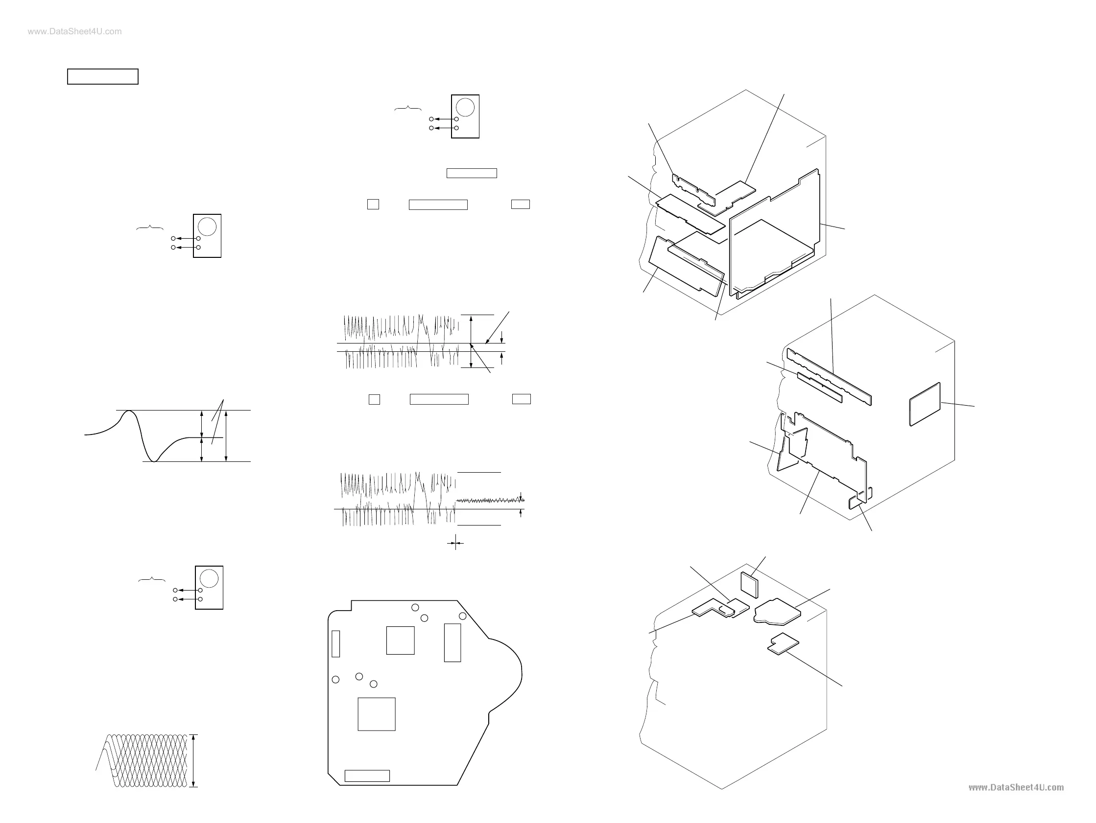
S Curve Check
Procedure :
1. Connect oscilloscope to test point TP (FEO).
2. Connect between test point TP (FOK) and Ground by lead wire.
3. Turn Power switch on.
4. Put disc (YEDS-18) in and turned Power switch on again and
actuate the focus search. (actuate the focus search when disc
table is moving in and out.)
5. Check the oscilloscope waveform (S-curve) is symmetrical be-
tween A and B. And confirm peak to peak level within 3 ± 1Vp-p.
S-curve waveform
6. After check, remove the lead wire connected in step 2.
Note: • Try to measure several times to make sure than the ratio of
A : B or B : A is more than 10 : 7.
• Take sweep time as long as possible and light up the bright-
ness to obtain best waveform.
RF Level Check
Procedure :
1. Connect oscilloscope to test point TP (RF) on BD board.
2. Turned Power switch on.
3. Put disc (YEDS-18) in and playback.
4. Confirm that oscilloscope waveform is clear and check RF sig-
nal level is correct or not.
Note: Clear RF signal waveform means that the shape “◊” can be
clearly distinguished at the center of the waveform.
RF signal waveform
VOLT/DIV : 200mV
TIME/DIV : 500ns
level : 1.3
±
0.3 Vp-p
oscilloscope
BD board
TP (RF)
TP (VC)
+
–
symmetry
A
B
Within 3
±
1 Vp-p
oscilloscope
BD board
TP (TE)
TP (VC)
+
–
E-F Balance (Traverse) Check
Procedure :
1. Connect oscilloscpe to test point TP (TEO) on BD board.
2. Turned Power switch on. Press FUNCTION button to select
CD.
3. Put disc (YEDS-18) in to play the number five track.
4. Press the p button, ENTER/NEXT button and ^ button
simultaneously several times until the ‘’SHUFFLE” on the
fluorescent display tube blinks.
(The sledding servo is turned OFF.)
5. Check the level B of the oscilliscope’s waveform and the A (DC
voltage) of the center of the Traverse waveform.
Confirm the following :
A/B x 100 = less than ± 7%
Traverse waveform
0V
level : 500 mV
±
100 mVp-p
A (DC voltage)
Center of the waveform
B
6. Press the p button, ENTER/NEXT button and ^ button
simultaneously several times until the ‘’SHUFFLE” on the
fluorescent display tube goes off. (The tracking servo and
sledding servo are turned ON.) Confirm the C (DC voltage) is
almost equal to the A (DC voltage) is step 5.
Traverse waveform
0V
C (DC
voltage)
Sled servo
OFF
Sled servo
ON
Adjustment Location :
[ BD BOARD ] — SIDE A —
TP (RF)
TP
(FOK)
IC101
TP
(VC)
TP
(GND)
TP
(TEO)
TP
(FEO)
IC103
IC102
IC102
CN101
oscilloscope
BD board
TP (FEO)
TP (VC)
+
–
SECTION 7
DIAGRAMS
7-1. CIRCUIT BOARDS LOCATION
SENSOR board
CONNECTOR board
BD board
MOTOR (SLIDE) boar
MOTOR (TURN) board
– 20 –
POWER board
CONT COM board
AUDIO board
LEAF SW board
TRANSFORMER board
MAIN boar
CD-SW board
MIC board
PANEL board
HP board
ENCAPSULATED
COMPONENT (GRX8/R800)
TCB board (RX88/RX99)
DECO board