EasyManua.ls Logo

Sony HCD-RX88 User Manual

Sony HCD-RX88
101 pages
To Next Page IconTo Next Page
Page #1 background imageLoading...
Page #1 background image
Sony Corporation
Home A&V Products Company
MHC-GRX8/R800/RX88/RX99
HCR-GRX8/R800/RX99
SERVICE MANUAL
MICROFILM
9-922-784-11
98B001671-1
Printed in Japan ©1998.2
Published by General Engineering Dept.
(Shibaura)
MHC-GRX8/R800/RX88/RX99 is composed of following
models.
As for the service manual, it is issued for each component
model, then, please refer to it.
AEP Model
UK Model
MHC-RX88/RX99
E Model
MHC-GRX8/R800
Australian Model
MHC-GRX8
PARTS LIST
Ref.No. Part No. Description Remark
–––––– ––––––– ––––––––– ––––––
ACCESSORIES & PACKING MATERIALS
********************************
1-475-571-11 COMMANDER, STANDARD (RM-SR8)
1-501-374-11 ANTENNA, LOOP
1-501-659-41 ANTENNA (FM) (GRX8/R800)
1-501-804-11 ANTENNA (FM) (RX88/RX99)
1-769-317-11 CORD, SPEAKER (2.5m) (FRONT SPEAKER)
1-769-433-11 CORD, SPEAKER(10m) (SURROUND SPEAKER)
3-862-011-11 MANUAL, INSTRUCTION (ENGLISH)
(EXCEPT G, TH)
3-862-011-21 MANUAL, INSTRUCTION (FRENCH, SPANISH)
(AEP, E, SP, MY, MX, AR, EA3)
3-862-011-31 MANUAL, INSTRUCTION (CHINESE)
(E, SP, MY, HK, TW)
3-862-011-41 MANUAL, INSTRUCTION (ARABIC) (EA3)
3-862-011-51 MANUAL, INSTRUCTION (GERMAN) (AEP, G)
MINI Hi-Fi COMPONENT SYSTEM
SPECIFICATIONS
Abbreviation
G : German model
EE : East European model
SP : Singapore model
MY : Malaysia model
MX : Mexican model
AR : Argentine model
EA3 : Saudi Arabia model
HK : Hong kong model
TW : Taiwan model
TH : Thai model
HCR-GRX8 is composed of HCD-GRX8 and SS-SR110
HCR-R800 is composed of HCD-R800 and SS-SR110
HCD-RX99 is composed of HCD-RX99 and SS-SR110
COMPONENT MODEL NAME FOR MHC-GRX8/R800/RX88/RX99
MHC-GRX8 MHC-R800 MHC-RX88 MHC-RX99
COMPACT DISC DECK
RECEIVER SYSTEM
HCD-GRX8 HCD-R800 HCD-RX88 HCD-RX99
FRONT SPEAKER SYSTEM SS-GRX8 SS-R800 SS-RX88 SS-RX99
SURROUND SPEAKER SYSTEM SS-SR110 SS-SR110
General
Power requirements
European models: 230 V AC, 50/60 Hz
Other models: 120 V, 220 V or 230 - 240 V AC, 50/60 Hz.
Adjustable with the voltage selector
Power consumption
MHC-GRX8/R800: 270 watts
MHC-RX88/RX99: 240 watts
Supplied accessories
AM loop antenna (1)
Remote RM-SR8
Batteries (2)
FM lead antenna (1)
Speaker cords (4)
Front speaker pads (8)
Design and specifications are subject to change without notice.
3-862-011-61 MANUAL, INSTRUCTION
(DUTCH, ITALIAN, PORTUGUESE) (AEP)
3-862-011-71 MANUAL, INSTRUCTION
(DANISH, FINNISH, SWEDISH) (AEP)
3-862-011-81 MANUAL, INSTRUCTION (POLISH, RUSSIAN)
(AEP, EE, CIS)
3-862-012-11 MANUAL, INSTRUCTION (HUNGARIAN)
(AEP,EE,CIS)
3-862-012-21 MANUAL, INSTRUCTION (CZECH) (AEP)
3-862-012-31 MANUAL, INSTRUCTION (GREEK) (AEP)
3-862-012-41 MANUAL, INSTRUCTION (TURKISH) (AEP)
3-862-015-31 MANUAL, INSTRUCTION (ENGLISH, THAI) (TH)
3-862-818-11 MANUAL, INSTRUCTION (ENGLISH, FRENCH,
GERMAN, SWEDISH, RUSSIAN)
(For SS-RX88/RX99)
4-991-151-21 COVER, BATTERY (FOR RM-SR8)
Ref.No. Part No. Description Remark
–––––– ––––––– ––––––––– ––––––
www.DataSheet4U.com

Table of Contents

Question and Answer IconNeed help?

Do you have a question about the Sony HCD-RX88 and is the answer not in the manual?

Sony HCD-RX88 Specifications

General IconGeneral
BrandSony
ModelHCD-RX88
CategoryStereo System
LanguageEnglish

Summary

SERVICING NOTE

Disc Tray Opening Procedure

Step-by-step instructions for opening the disc tray with the power off.

Rotary Encoder Installation Note

Specific notes for installing the rotary encoder component.

GENERAL

Front Panel Overview

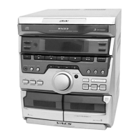
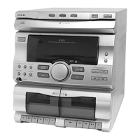
Identifies and illustrates the various controls and parts on the front panel.

Location of Parts and Controls

Detailed list and explanation of all parts and controls on the unit.

DISASSEMBLY

Component Disassembly Steps

Steps for disassembling loading panel, front panel, and cassette deck.

Board and Tray Disassembly

Instructions for disassembling panel boards, CONT COM board, and disc tray.

SERVICE MODE

Service Mode Functions

Details various service modes like reset, delivery, servo, tuner step, and key check.

AGING MODE

Purpose and Preparation

Explains the aging mode, preparations, sequence, and status displays for CD and tape decks.

MECHANICAL ADJUSTMENTS

Precautions and Torque Measurement

General precautions and torque measurement guidelines for mechanical adjustments.

ELECTRICAL ADJUSTMENTS

Deck Section Adjustments

Adjustments for the deck section, including azimuth and tape speed.

Tuner Section Adjustments

Covers AM/FM level and FM polar adjustments for specific regions.

TUNER SECTION

Notes on Tuner Repair and Adjustment

Notes regarding tuner front-end repair and adjustment requirements.

AM Tuned Level Adjustment

Procedure for adjusting the AM tuned level for specific models.

FM Tuned Level Adjustment

Steps to adjust the FM tuned level after AM adjustment.

FM Polar Adjustment

Procedure for FM polar adjustment specific to East European/CIS models.

CD SECTION

Optical Pick-Up and Laser Diode Handling

Precautions for handling optical pick-up and laser diode emission checks.

CD Performance Checks

Procedures for S-curve, RF level, and E-F balance checks.

DIAGRAMS

Circuit Boards Location

Illustrates the location of all circuit boards within the unit.

Block Diagrams

Block diagrams for Tuner, CD, Deck, Main, Power, and Display sections.

Printed Wiring Boards

PWB layouts for CD, Tuner, Deck, Main, Power, Mic/HP, Display, CD Motor sections.

Schematic Diagrams

Schematics for CD, Tuner, Deck, Main, Mic/HP, Power, Transformer, LEAF SW, Display, Panel sections.

IC Block Diagrams and Pin Functions

Block diagrams and pin functions for key ICs used in the unit.

EXPLODED VIEW AND PARTS LIST

Component Exploded Views

Exploded views and parts lists for Case, Chassis, Front Panel, CD Mechanism, Base Unit, and TC Mechanisms.

ELECTRICAL PARTS LIST

Parts Lists by Section

Electrical parts lists for Audio, Panel, Power, TCB, Transformer, Accessories, and Hardware.

Related product manuals